BBB-OLED
A small add-on for a plain BeagleBone Black running FPP: an OLED status display, four menu buttons, a real-time clock and a temperature sensor. It has no outputs of its own.
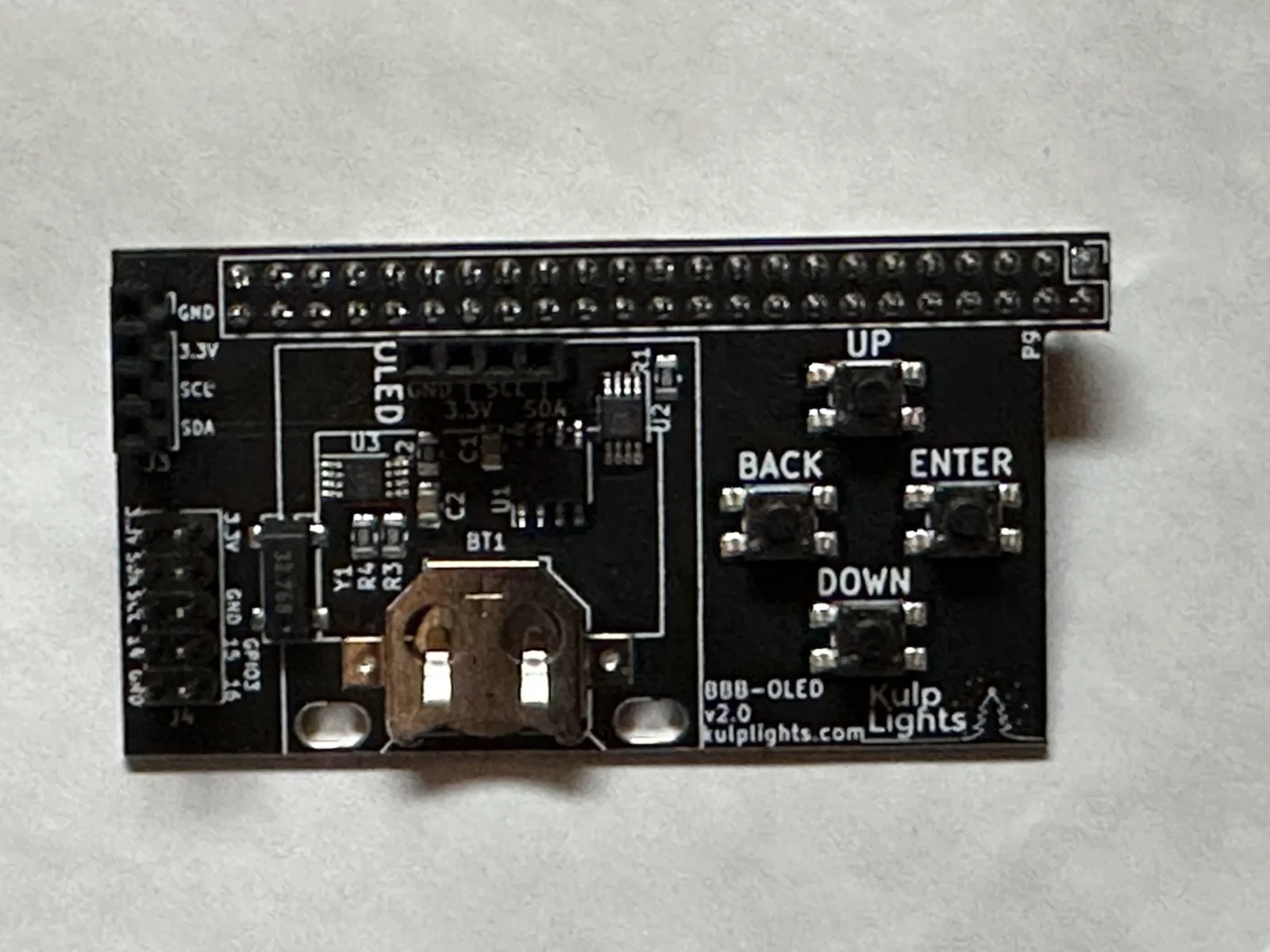
BBB-OLED (v2.0), shown without its display, which covers the clock battery.
This page describes revision v2.0 (printed on the board as BBB-OLED v2.0).
Use it on a BeagleBone that drives its lights over the network or USB, or plays the show as a player or master: it gives the BeagleBone the same display, menus and test buttons as the Kulp controllers. It plugs onto the BeagleBone's P9 header only.
Not with an output cape
The BBB-OLED uses pins on the P9 header that the BeagleBone Black output capes also use. Fit it to a BeagleBone without another cape.
Specifications
| BBB-OLED | |
|---|---|
| Display | 128×64 OLED, blue/yellow, fitted |
| Buttons | Up / Down / Back / Enter |
| Real-time clock | yes, CR1220 cell included |
| Temperature sensor | yes |
| Headers | 1×4 I²C socket; 2×5 I²C and GPIO header |
| Outputs | none |
| Power | from the BeagleBone |
| Size | 66.6 × 34.0 mm (2.62 × 1.34 in), no mounting holes |
| Requires | BeagleBone Black or compatible (see BeagleBone Black), FPP 9.5 or later |
Board map
Fitting it
- Disconnect power from the BeagleBone.
- Line the BBB-OLED's socket up with the P9 header: the end marked
P9goes at the BeagleBone's Ethernet end, with the board lying over the BeagleBone. - Press it down evenly until it is fully seated. It has no mounting holes; the header holds it.
The BBB-OLED takes its power from the BeagleBone. Power the BeagleBone from its barrel jack or USB as usual.
Buttons
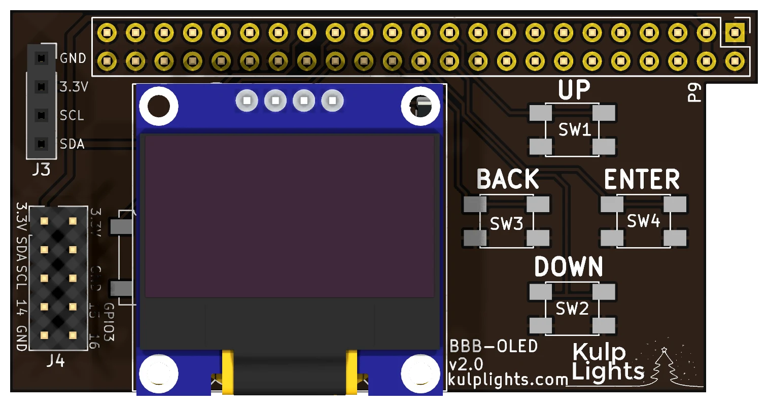
The four buttons are in a diamond at the right: UP at the top, BACK at the left, ENTER at the right and DOWN at the bottom. DOWN also works as Test on the status page. See Controls & display.
Clock
The real-time clock keeps time with no network. Its CR1220 cell sits under the display: unplug the display to change it. See Clock.
Headers
| Header | Marking | Details |
|---|---|---|
| I²C socket | J3: GND 3.3V SCL SDA |
1×4 socket at the top left, on the I²C bus, for an extra I²C sensor or device. |
| GPIO / I²C | J4: 3.3V SDA SCL 14 GND, 3.3V GND GPIO3 15 16 |
2×5 header below it, laid out like the first ten pins of a Raspberry Pi header: 3.3 V, GND, the I²C bus and three BeagleBone GPIOs (GPIO3_14, GPIO3_15 and GPIO3_16, on P9-31, P9-29 and P9-30). Unlike a Pi, it has 3.3 V only, no 5 V: some Pi I²C add-ons work if they run on 3.3 V. |
The GPIO pins are 3.3 V only: use them for buttons or switches to ground in FPP's GPIO Inputs.
FPP setup
When FPP detects the BBB-OLED it sets up the display, the buttons, the clock and the temperature sensor automatically.
Board revisions
| Revision | Changes |
|---|---|
| v1.0 | No real-time clock. |
| v2.0 | Adds the clock and its battery. |