K32-Pro
32 fused pixel ports, 8 two-way differential ports, audio and 2 DMX.
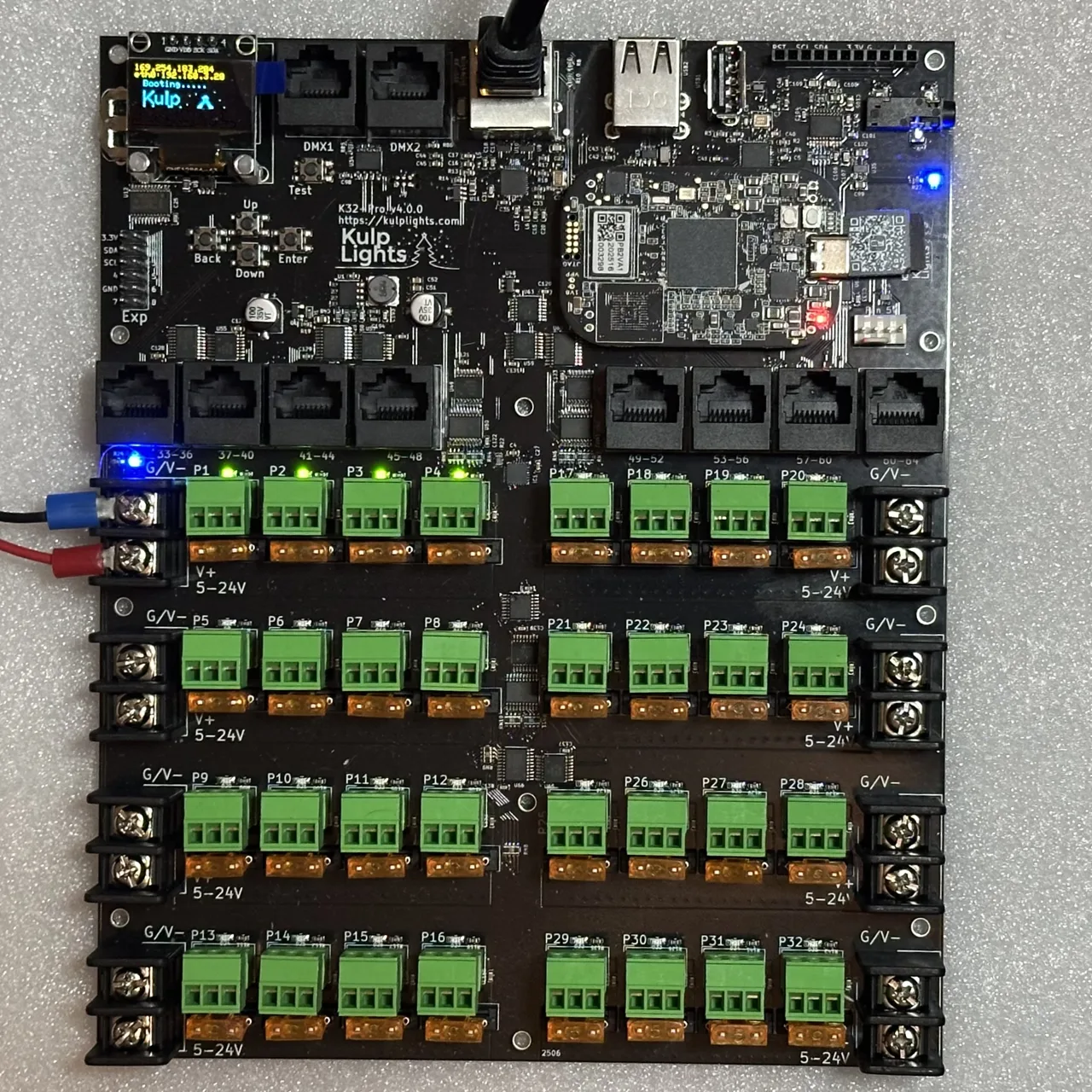
K32-Pro with a PocketBeagle 2 fitted. Photos may show an earlier board revision.
This page describes revision v4.1.0 (printed on the board as K32-Pro v4.1.0). Differences in earlier revisions are listed under Board revisions.
Specifications
| K32-Pro | |
|---|---|
| Local pixel ports | 32 (P1–P32), 3-pin 3.5 mm pluggable, plugs included |
| Port protection | 5 A mini-blade fuse per port |
| Power switching | per bank of 4, FPP-controlled (v4.1 and later) |
| Current monitoring | from Falcon V5 receivers only |
| Differential ports | 8 × RJ45 = 32 strings (33–64), two-way (pair 1/2) |
| Total strings | 64 |
| Power inputs | 8 terminals rated 30 A, 5–24 V DC, one bank of 4 ports each |
| DMX / serial | 2 (DMX1, DMX2), RS-485 transmit |
| Audio | PCM5102A DAC, 3.5 mm line out, FM transmitter socket |
| Ethernet | 1 × Gigabit (USB-attached) |
| USB-A | 3 |
| Display & buttons | 128×64 OLED, Up / Down / Enter / Back / Test |
| Real-time clock | yes, CR1220 backup cell |
| Fan header | 5 V 4-pin PWM, temperature-controlled; speed monitoring on v4.1 and later |
| Expansion header | 2×6: I²C + 8 GPIO (Exp.1–Exp.8) |
| Size | 168.6 × 202.8 mm (6.64 × 7.98 in), 11 mounting holes, 3.0 mm |
| Requires | PocketBeagle 2 (not PocketBeagle 1), FPP 9.0 or later |
Board map
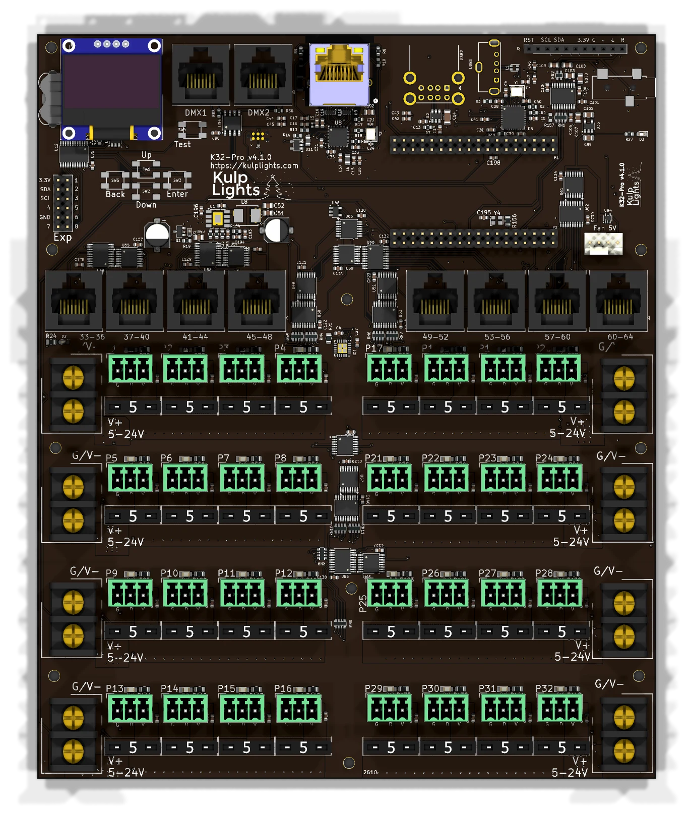
Power terminals
The four terminals down the left edge feed the left half of the board, and the four down the right edge feed the right half. FPP's VIN numbers don't follow reading order:
| Terminal | Position | Feeds | FPP reading | Also powers the controller? |
|---|---|---|---|---|
| V1 | left, row 1 (top) | P1–P4 | VIN1 | yes |
| V2 | left, row 2 | P5–P8 | VIN2 | no |
| V5 | left, row 3 | P9–P12 | VIN5 | no |
| V6 | left, row 4 | P13–P16 | VIN6 | no |
| V3 | right, row 1 (top) | P17–P20 | VIN3 | no |
| V4 | right, row 2 | P21–P24 | VIN4 | no |
| V7 | right, row 3 | P25–P28 | VIN7 | no |
| V8 | right, row 4 | P29–P32 | VIN8 | no |
The blue LED beside V1 lights when it has power. V1 must be powered for the controller to boot.
See Power for supply sizing, wire size and safety.
Pixel ports
The 32 pixel ports are in four rows of eight, four ports on each side:
| Left half | Right half | |
|---|---|---|
| Row 1 | P1–P4 | P17–P20 |
| Row 2 | P5–P8 | P21–P24 |
| Row 3 | P9–P12 | P25–P28 |
| Row 4 | P13–P16 | P29–P32 |
Each port is G D V (ground, data, +V), as printed beside it. See Pixel outputs.
Fuses
Every local port has a 5 A mini-blade fuse next to it. If a port's green LED is dark while the rest of its bank is lit, check that port's fuse first. Never fit a fuse larger than 5 A. See Power → Fuses.
Bank switching
Each bank of four ports has an electronic power switch that FPP controls, so FPP can turn pixel power off when nothing is playing. See Power → Bank switching.
Bank switching was added in v4.1. On a v4.0 board every bank is on whenever it has power. See Board revisions.
Differential ports
33-36 · 37-40 · 41-44 · 45-48 · 49-52 · 53-56 · 57-60 · 61-64
Each jack carries four strings, numbered as printed above it. They are two-way: Falcon V5 smart receivers report their eFuse status and current back over pair 1/2. Other receivers work as send-only. See Differential ports.
Note
On earlier boards the last differential jack is printed 60-64. It carries strings 61–64.
Other connectors
| Connector | Marking | Details |
|---|---|---|
| Ethernet | (RJ45 with LEDs) | Network |
| DMX | DMX1, DMX2 |
DMX / serial |
| USB-A | — | 3 ports, USB |
| OLED | GND 3.3V SCL SDA |
Controls & display |
| Audio out | 3.5 mm jack | Audio |
| FM transmitter | RST SCL SDA 3.3V G L R |
Audio |
| Fan | Fan 5V |
Fan |
| Expansion | Exp |
Expansion header |
| RTC battery | coin-cell holder | Clock |
FPP setup
When FPP detects the K32-Pro it sets itself up automatically. It enables the K32-Pro pixel-string layout, the sensors (input voltages, temperature), the audio output and a disabled DMX output. Out of the box each local port is set to 50 WS2811 pixels at 50 % brightness. Set the real counts and start channels from xLights or the FPP Pixel Strings page. See Configuring outputs.
Board revisions
The revision is printed on the board next to the model name. FPP also shows it as the Hardware Version under Help → About → Cape Info.
| Revision | Changes |
|---|---|
| v4.0 | Fused ports; banks are always on when powered. Fan speed control. |
| v4.1 | Adds bank switching (FPP turns each bank of 4 on and off) and fan speed monitoring. |
Dimensions & mounting
- 168.55 × 202.75 mm (6.64 × 7.98 in), 11 plated mounting holes, 3.0 mm, for M2.5 (or #4) screws and standoffs.
- The mounting holes are connected to ground.
- Use nylon or metal standoffs at least 6 mm (¼ in) tall, so nothing on the underside touches the enclosure.
- Mounting drawing: PDF · SVG. It is shared by the K32, K32-Pro and K32-Max, which have the same outline and holes.
- A 3D-printable mount is on Thingiverse.
