Kulp Lights Controller Manual
| Description | Hardware manual for Kulp Lights PocketBeagle2 pixel controllers running FPP |
| Author(s) | Kulp Lights |
| Repository | https://github.com/KulpLights/kulp-manuals |
| Copyright | Copyright © 2026 Kulp Lights |

Kulp Lights Controller Manual¶
This manual covers the hardware of the Kulp Lights controllers.
PocketBeagle 2 controllers¶
-
K8-Pro · K8-Max
8 local pixel ports + 4 differential ports (16 strings).
-
K8-PB · K4-PB · K40D-PB
Compact: 8 or 4 local pixel ports, or 40 strings on 10 differential ports (K40D-PB).
-
K16 · K16-Pro · K16-Max
16 local pixel ports + 4 or 8 differential ports.
-
K32 · K32-Pro · K32-Max
32 local pixel ports + 4 or 8 differential ports.
-
PocketScroller v2 · v3 · -16
6, 8 or 16 HUB75 outputs for LED panel matrices.
BeagleBone Black controllers¶
-
K8-B · K8-B-Scroller
8 fused pixel ports + differential ports; the K8-B-Scroller adds 3 HUB75 panel outputs.
-
K64D-B · K128D-B
64 or 128 strings on 16 or 32 differential ports, with audio and two DMX/LOR outputs.
-
OctoPlus
8 HUB75 outputs for LED panel matrices.
Raspberry Pi controllers¶
-
K8-Pi
8 eFused pixel ports + 3 differential ports and an expansion port: 36 strings.
-
K2-Pi-Servo · K2-Pi0
2 eFused pixel ports, plus 16 servo outputs (K2-Pi-Servo) or on a Pi Zero (K2-Pi0).
Displays & add-ons¶
Every one of these boards is a cape (or hat) for a PocketBeagle 2, a BeagleBone Black or a Raspberry Pi and runs FPP (Falcon Player). FPP is the software that plays your show, and it has its own manual at manual.falconplayer.com. This manual doesn't repeat that one. It covers what the FPP manual can't:
- Power: wiring power supplies, banks, fuses and eFuses.
- Pixel outputs and differential ports: wiring pixels and receivers.
- Controls & display: the buttons, the OLED menus and the status LEDs.
- Board pages: one per controller, with specifications, connector maps and dimensions.
- Troubleshooting for hardware problems.
Read the Safety page before you connect a power supply.
Where to start¶
- Not sure which board you have? See Which board do I have?
- Setting one up for the first time? Follow the Quick start checklist.
- Something not working? Go to Troubleshooting.
Printing or saving a PDF
The Print / PDF page puts the whole manual on one page. Use your browser's Print → Save as PDF to save it as a PDF.
Found a mistake or something missing? Email support@kulplights.com or use the edit link at the top of any page.
Getting Started
Safety¶
These controllers run on low-voltage DC (5–24 V) but can switch a lot of current. A K32 with every port loaded can deliver well over 100 A across its banks. At that level, the hazards are fire from loose or undersized wiring, and the mains (AC) side of your power supplies.
Mains voltage
- Never connect household AC (120/230 V) to any terminal on the controller. The controller only accepts DC from a power supply.
- Have the AC side of your power supplies wired by someone qualified. Use grounded (3-prong) cords and close the terminal covers on the supply.
- If a supply has a 115V/230V input switch, set it to match your mains before you plug it in. The wrong setting can destroy the supply.
- Unplug the AC before you touch the supply's output terminals or the controller's power terminals.
Fire prevention
- Never fit a larger fuse than the one supplied, and never bridge a fuse holder. The fuse protects the pixel wiring; a bigger fuse lets that wiring overheat.
- Use wire rated for the current it carries (see Power → Wire size). Tighten every screw terminal firmly. A loose terminal heats up under load.
- Tin or ferrule stranded wire ends. Stray strands can short to the next terminal.
- Mount the controller in an enclosure, away from flammable material. Leave room for airflow, especially around the power terminals and the eFuse/fuse area.
Polarity and voltage
- Check V+ and G/V− on every terminal before you power up. On the K8, K16 and K32 boards the power inputs have reverse-polarity protection, so reversed power won't damage the controller; that bank simply stays off. The K8-PB and K4-PB have no such protection, and a reversed supply can damage them. Pixels have no such protection either. Wiring a pixel string backwards, or running 5 V pixels from a 12 V bank, will destroy the pixels.
- Every pixel port on a bank gets the voltage of that bank's power supply. Check that the supply voltage matches the pixels on every port in the bank.
- The K40D-PB and the PocketScrollers accept 5 V only. Do not connect 12 V or 24 V to them.
Outdoors
The controller is not waterproof. Outdoors, mount it in a weather-resistant enclosure with drip loops on every cable, and keep the power supplies in an enclosure too. Condensation and insects cause more failures than rain does.
Making connections
Turn the power off before you plug or unplug pixel connectors, receivers or power terminals. Network, USB, audio and DMX cables can be connected with the power on.
Storage
If you store the controller for a long time, take out the clock (RTC) coin cell. That keeps it from draining and leaking.
Which board do I have?¶
Every board has its model and revision printed on it, next to the Kulp Lights logo
(for example K16-Max v4.1.0). FPP also shows the model on its Status page and under
Help → About.
To tell them apart at a glance:
| What you see | Board |
|---|---|
| 8 green pixel plugs, mini-blade fuses along the bottom edge | K8-Pro |
| 8 green pixel plugs, no fuses | K8-Max |
| 8 green pixel plugs on a small (74 × 97 mm) board, 3 RJ45s, no Ethernet jack, a 24-pin header on the left edge | K8-PB |
| 10 RJ45 jacks (5 along the top, 5 along the bottom) and no pixel plugs | K40D-PB |
| 4 green pixel plugs in one row on a small (71 × 67 mm) board, no RJ45 jacks | K4-PB |
16 pixel plugs with fuses, 4 port RJ45s, one DMX jack |
K16 |
16 pixel plugs with fuses, 8 port RJ45s, DMX1/DMX2 |
K16-Pro |
| 16 pixel plugs, no fuses, 8 port RJ45s | K16-Max |
32 pixel plugs with fuses, 4 port RJ45s, one DMX jack |
K32 |
32 pixel plugs with fuses, 8 port RJ45s, DMX1/DMX2 |
K32-Pro |
| 32 pixel plugs, no fuses, 8 port RJ45s | K32-Max |
| 6 ribbon-cable (HUB75) headers along the bottom edge, no Ethernet jack | PocketScroller v2 |
| 8 ribbon-cable (HUB75) headers marked Output 1–8 | PocketScroller v3 |
| 16 ribbon-cable (HUB75) headers in two rows, Output 1–16 | PocketScroller-16 |
| 8 green pixel plugs with fuses, 3 RJ45s on the left edge, a 40-pin header along the top, a BeagleBone underneath | K8-B |
| 8 green pixel plugs with fuses, 1 RJ45 and 3 ribbon-cable (HUB75) headers marked Panel 1–3 | K8-B-Scroller |
| 16 RJ45 jacks in a 4 × 4 grid, a BeagleBone upside down on top | K64D-B |
| 32 RJ45 jacks in 8 rows of 4, a BeagleBone upside down on top | K128D-B |
| 8 ribbon-cable (HUB75) headers in two rows of four, on a cape the size of a BeagleBone | OctoPlus |
16 pixel plugs, 4 RJ45s in a 2 × 2 block, ttyS1/ttyS2 on the left edge, a BeagleBone underneath |
K16A-B (retired) |
| 32 pixel plugs with fuses along the top and bottom edges, 4 RJ45s in a 2 × 2 block, a BeagleBone underneath | K32A-B (retired) |
| An OLED and 4 buttons on a small board plugged onto one BeagleBone header, no outputs | BBB-OLED |
| An OLED and 4 buttons on a Raspberry Pi, no outputs (the full-size one has a 3.5 mm jack) | Pi-OLED |
| 8 green pixel plugs, no fuses, 3 RJ45s along the top, a Raspberry Pi underneath | K8-Pi |
| 2 pixel plugs and 16 three-pin servo headers, on a Raspberry Pi | K2-Pi-Servo |
| 2 pixel plugs on a small (65 × 30 mm) board, on a Raspberry Pi Zero | K2-Pi0 |
-
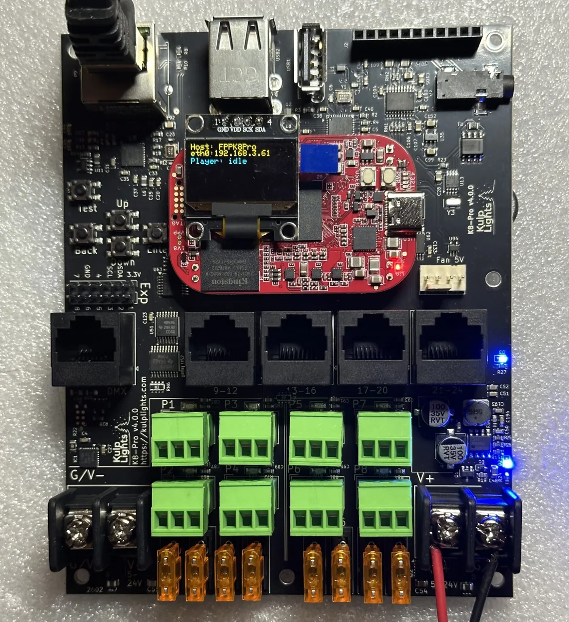
K8-Pro
-
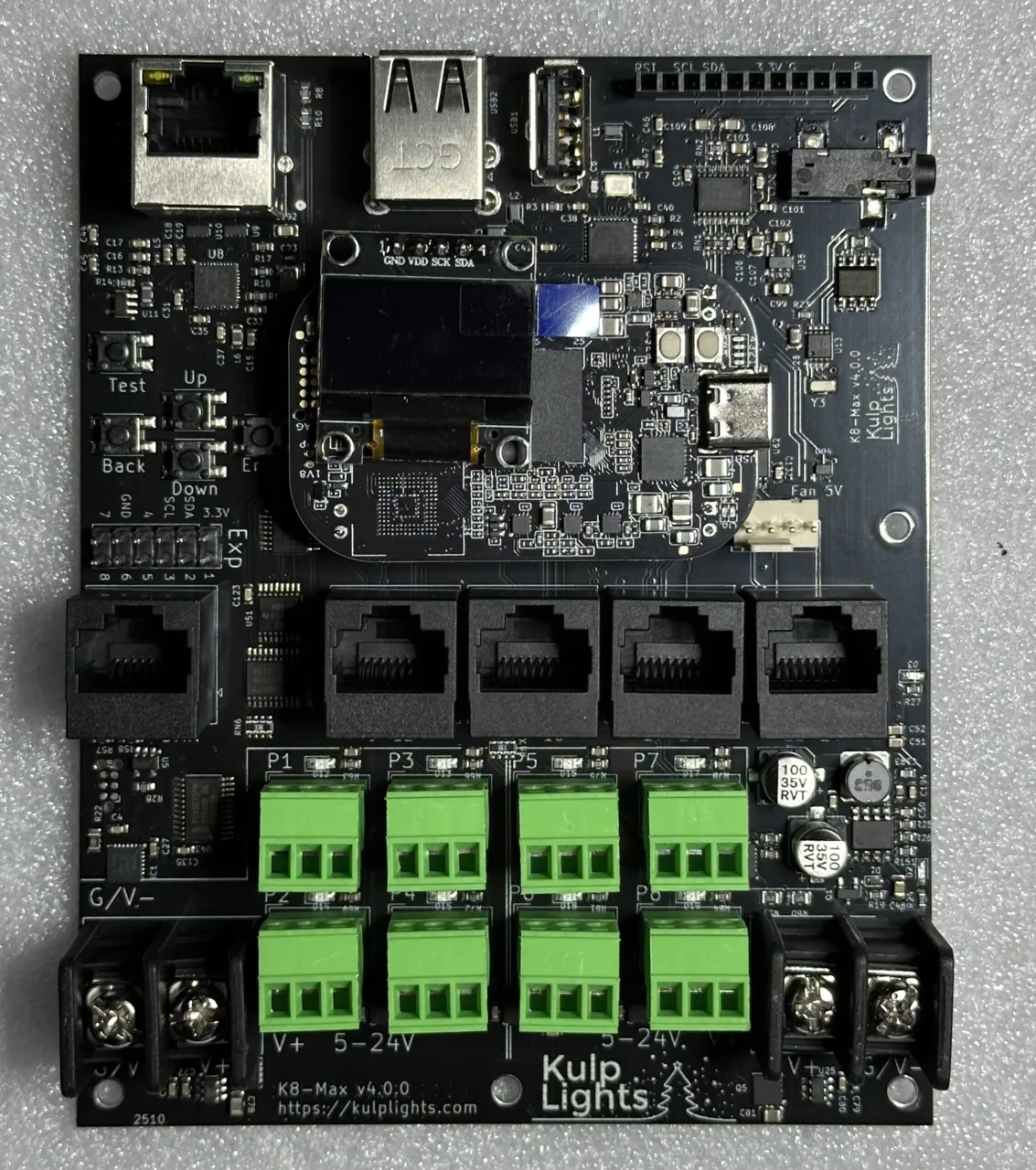
K8-Max
-
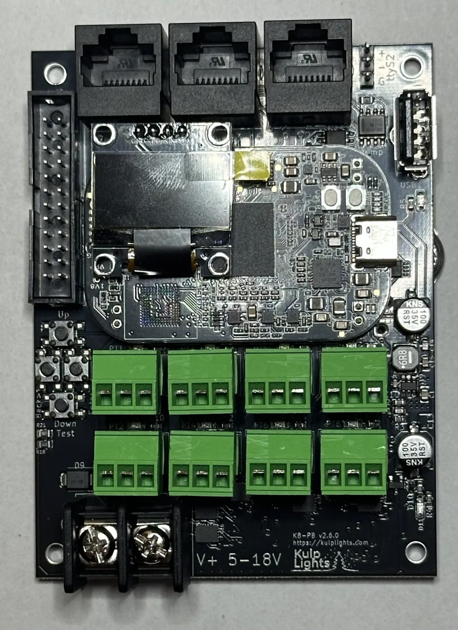
K8-PB
-
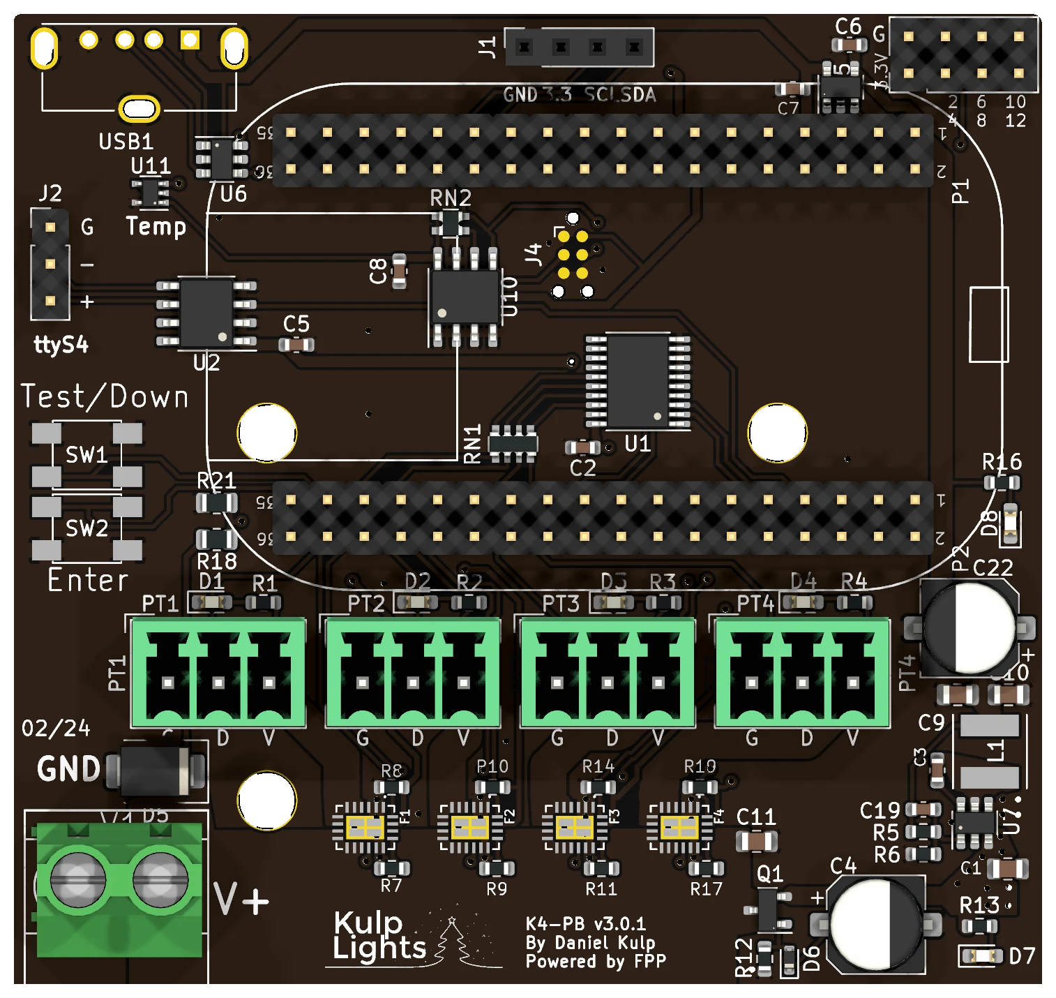
K4-PB (rendering)
-
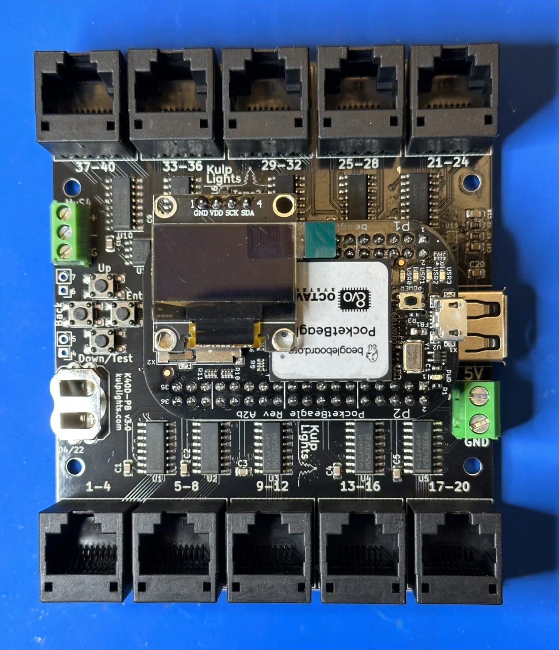
K40D-PB
-
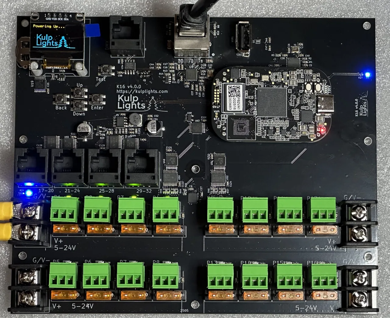
K16
-
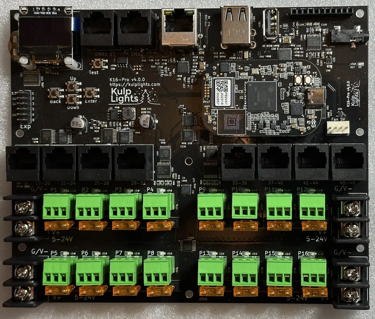
K16-Pro
-
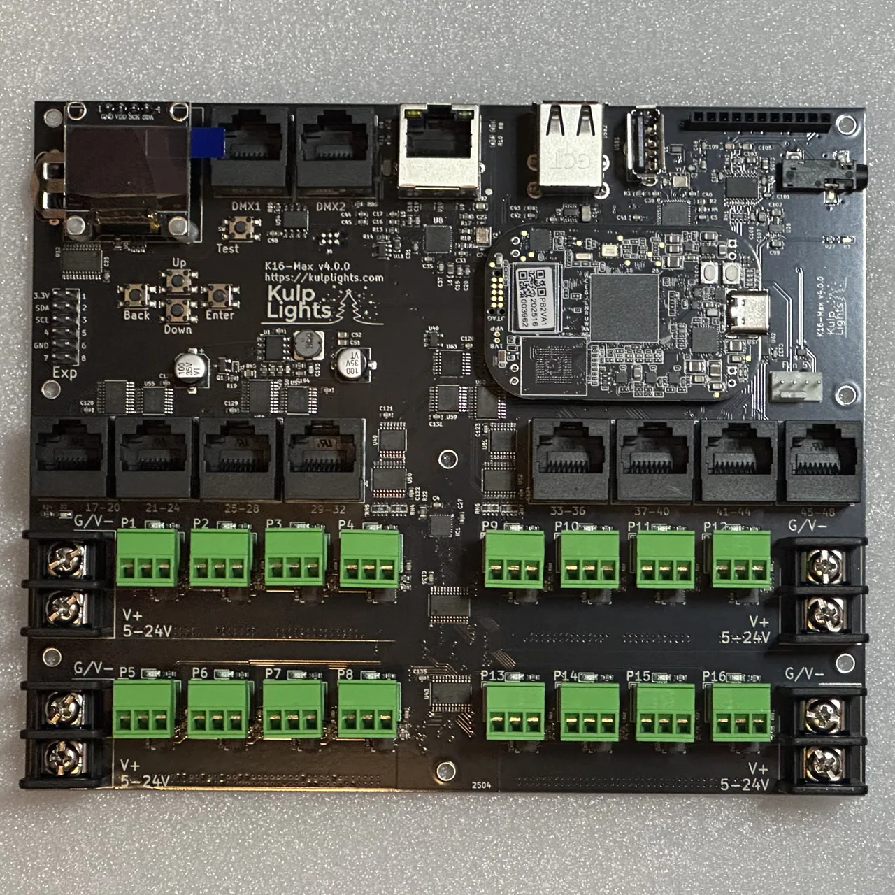
K16-Max
-
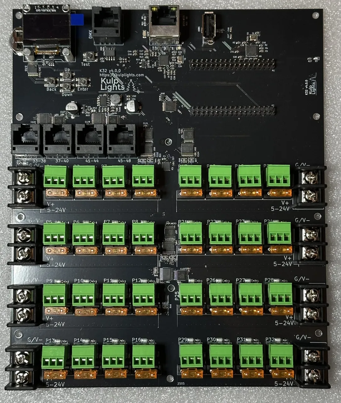
K32
-
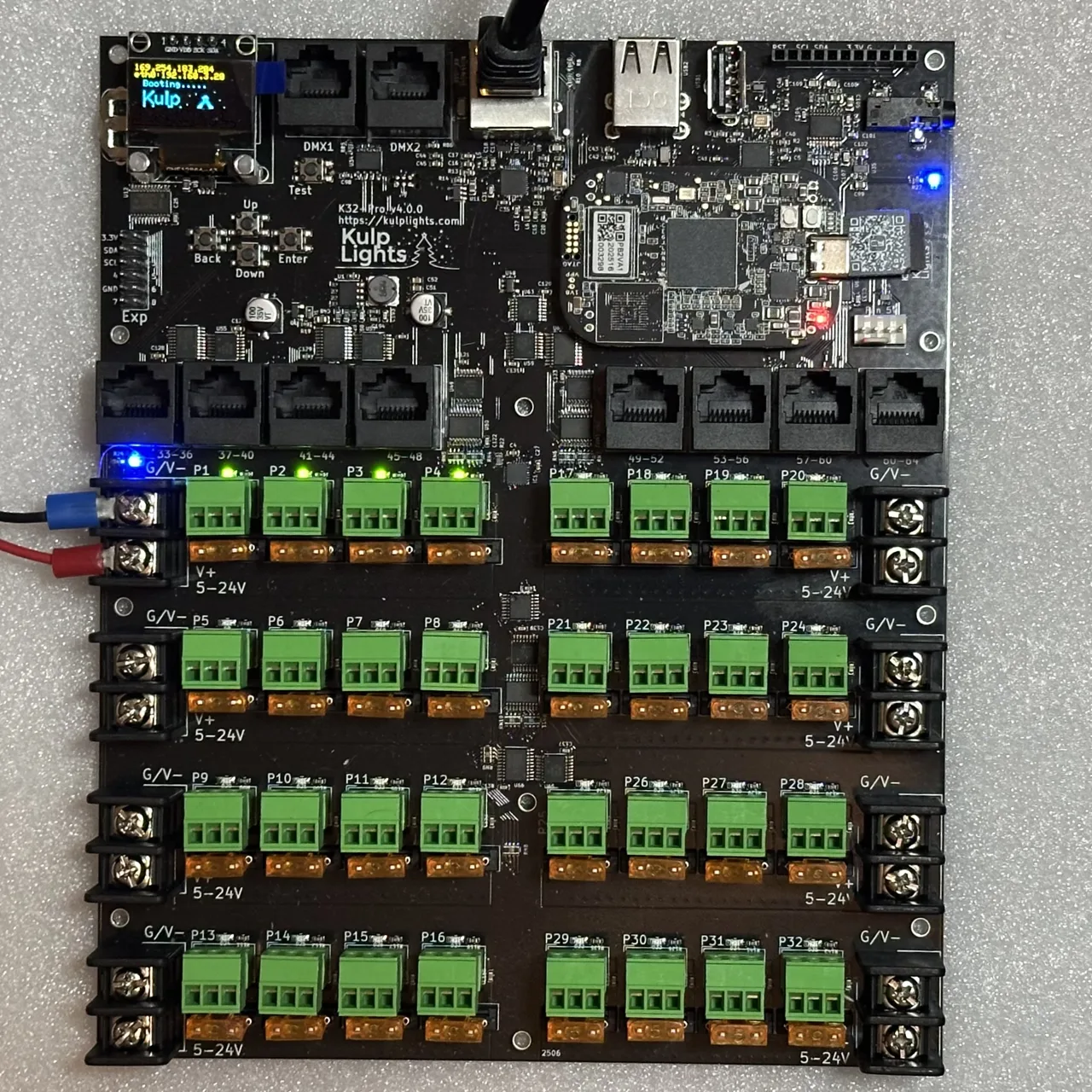
K32-Pro
-
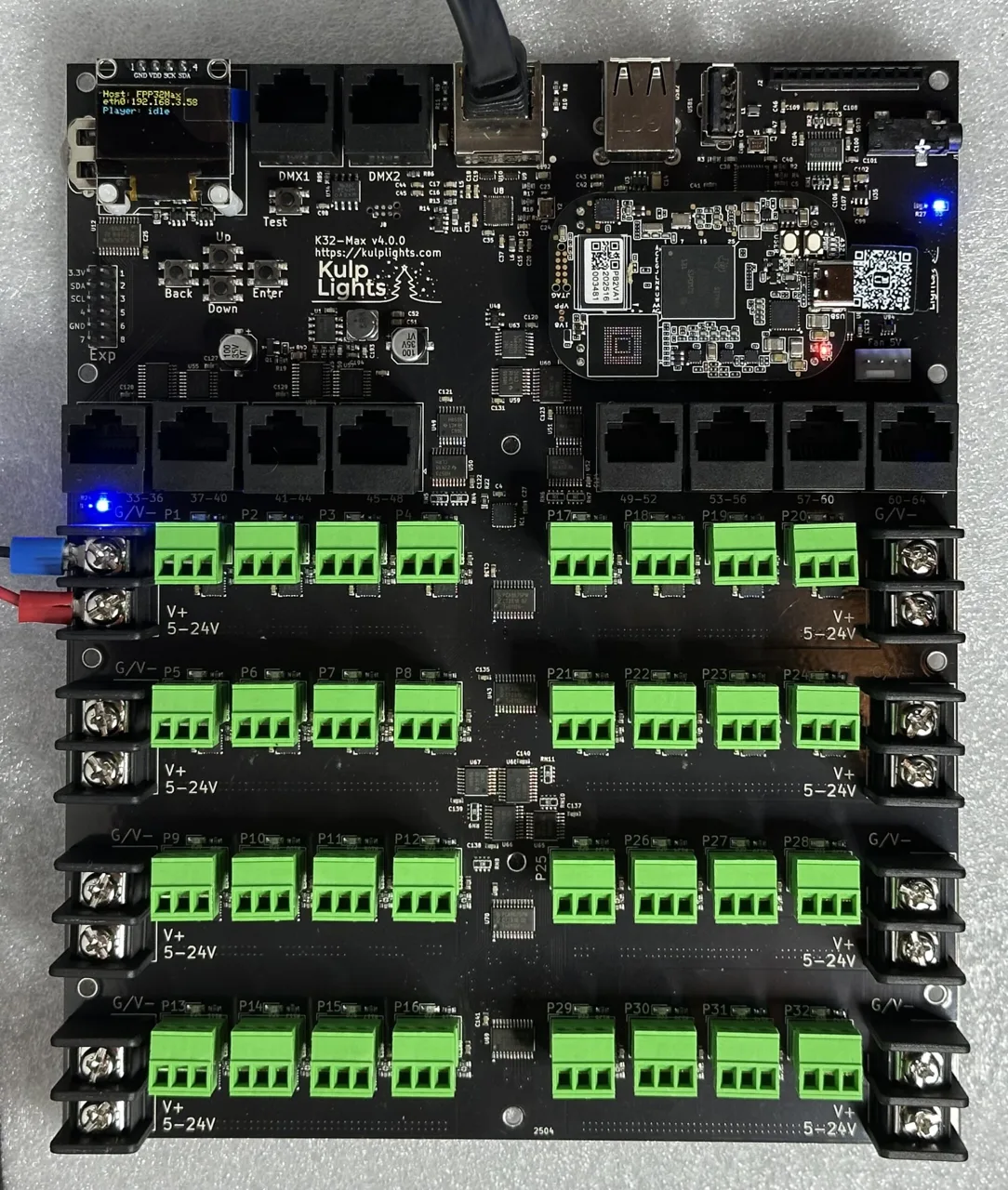
K32-Max
-
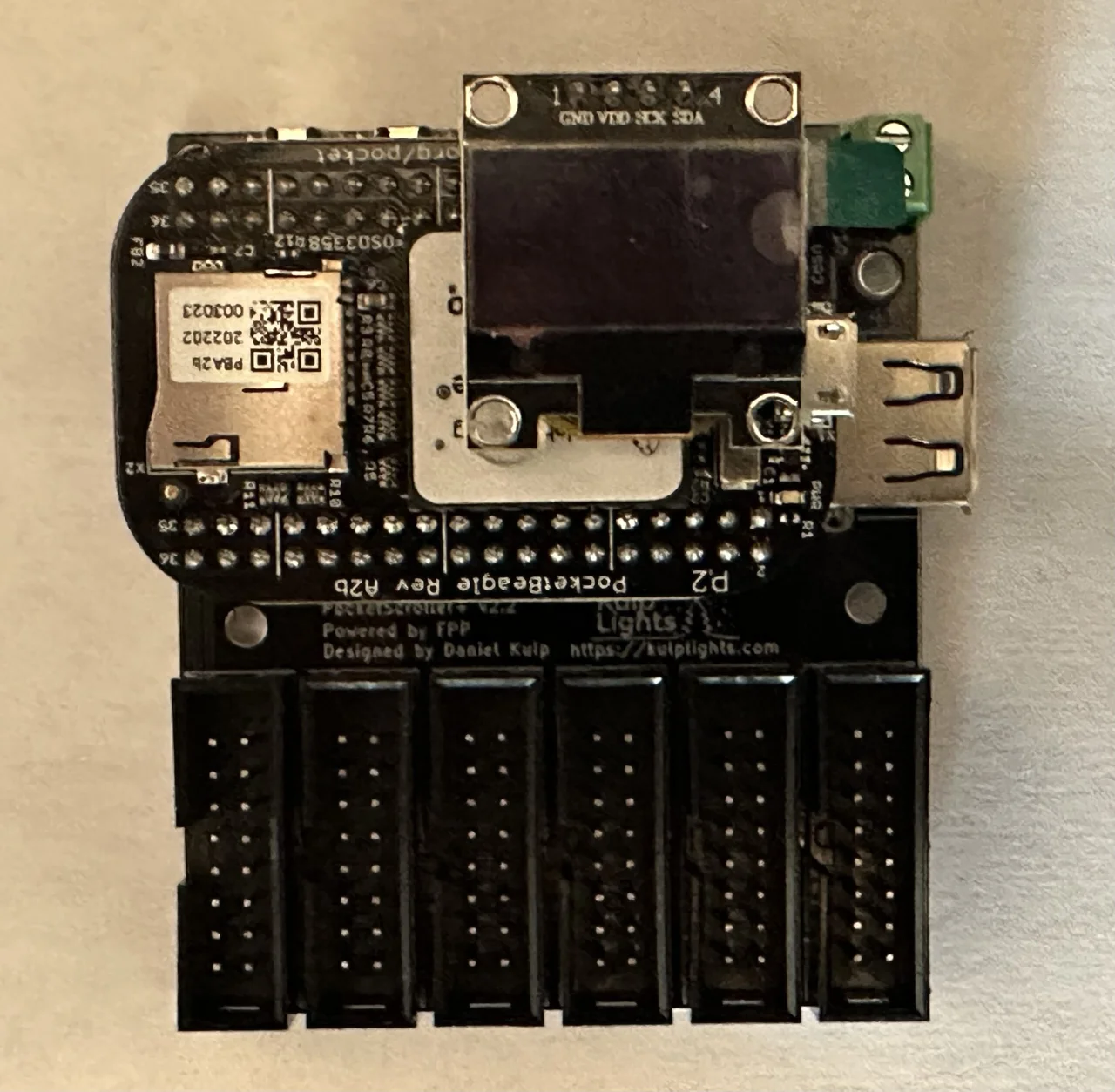
PocketScroller v2
-
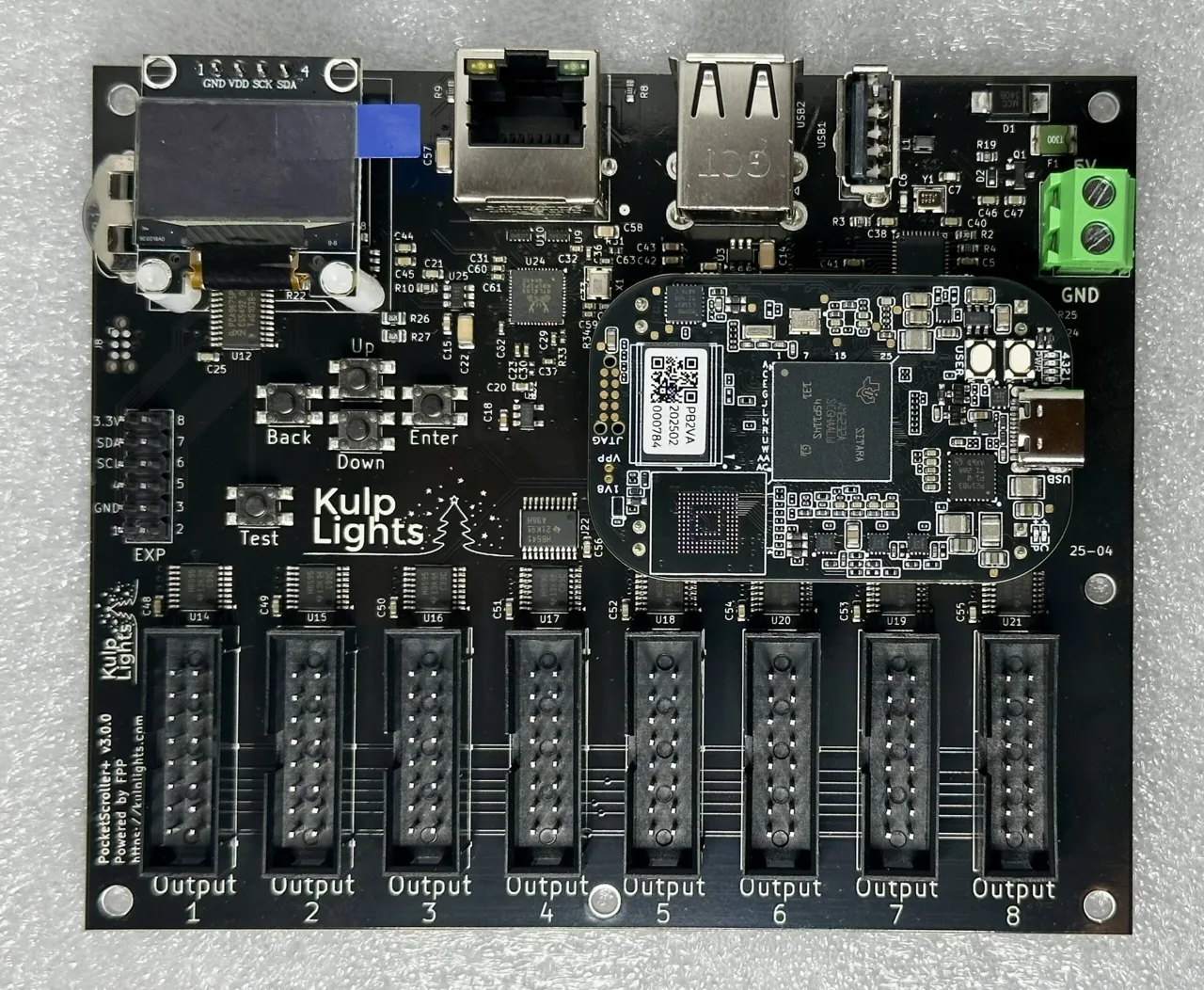
PocketScroller v3
-
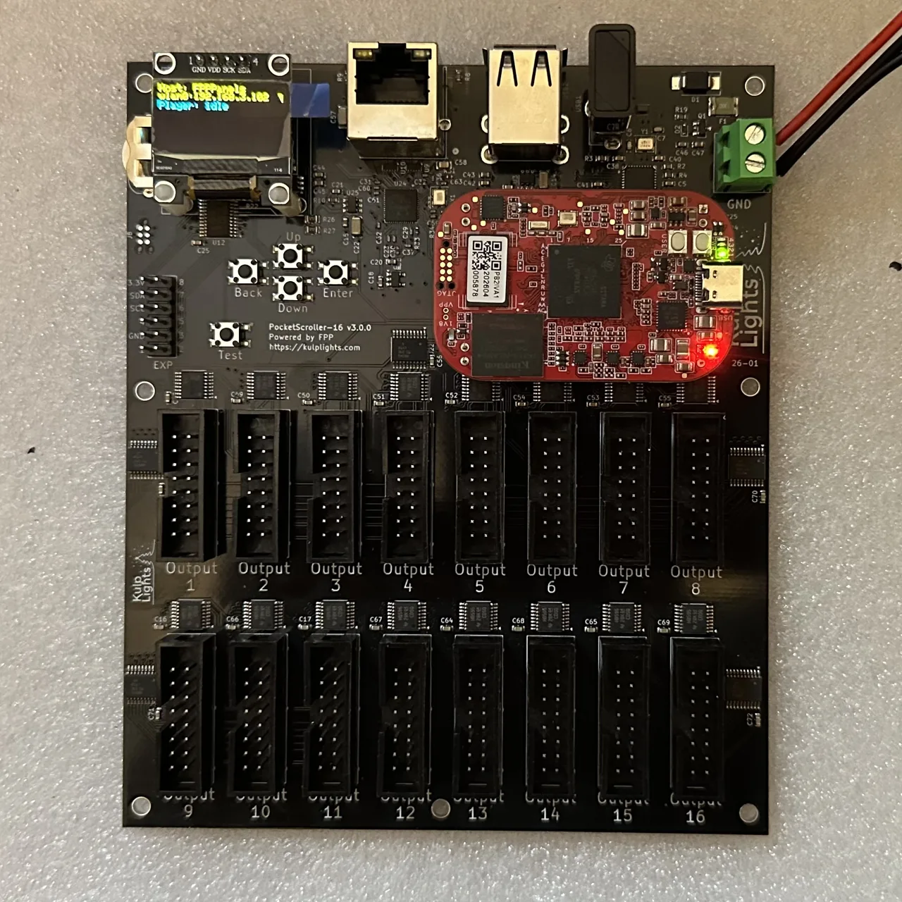
PocketScroller-16
-
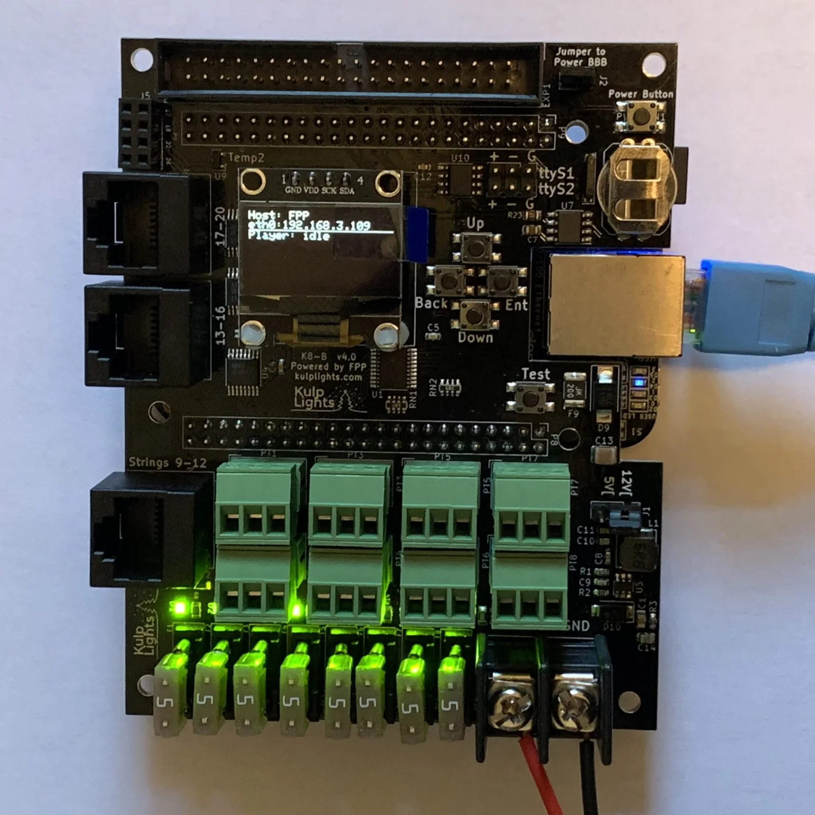
K8-B
-
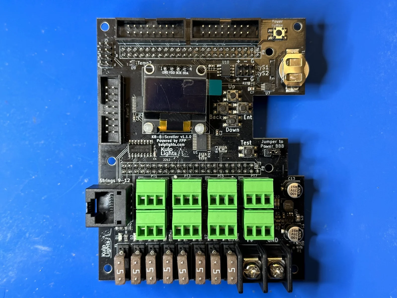
K8-B-Scroller
-
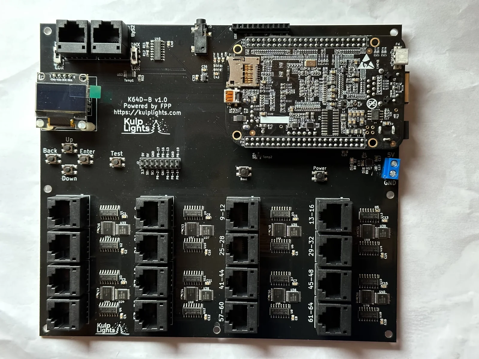
K64D-B
-
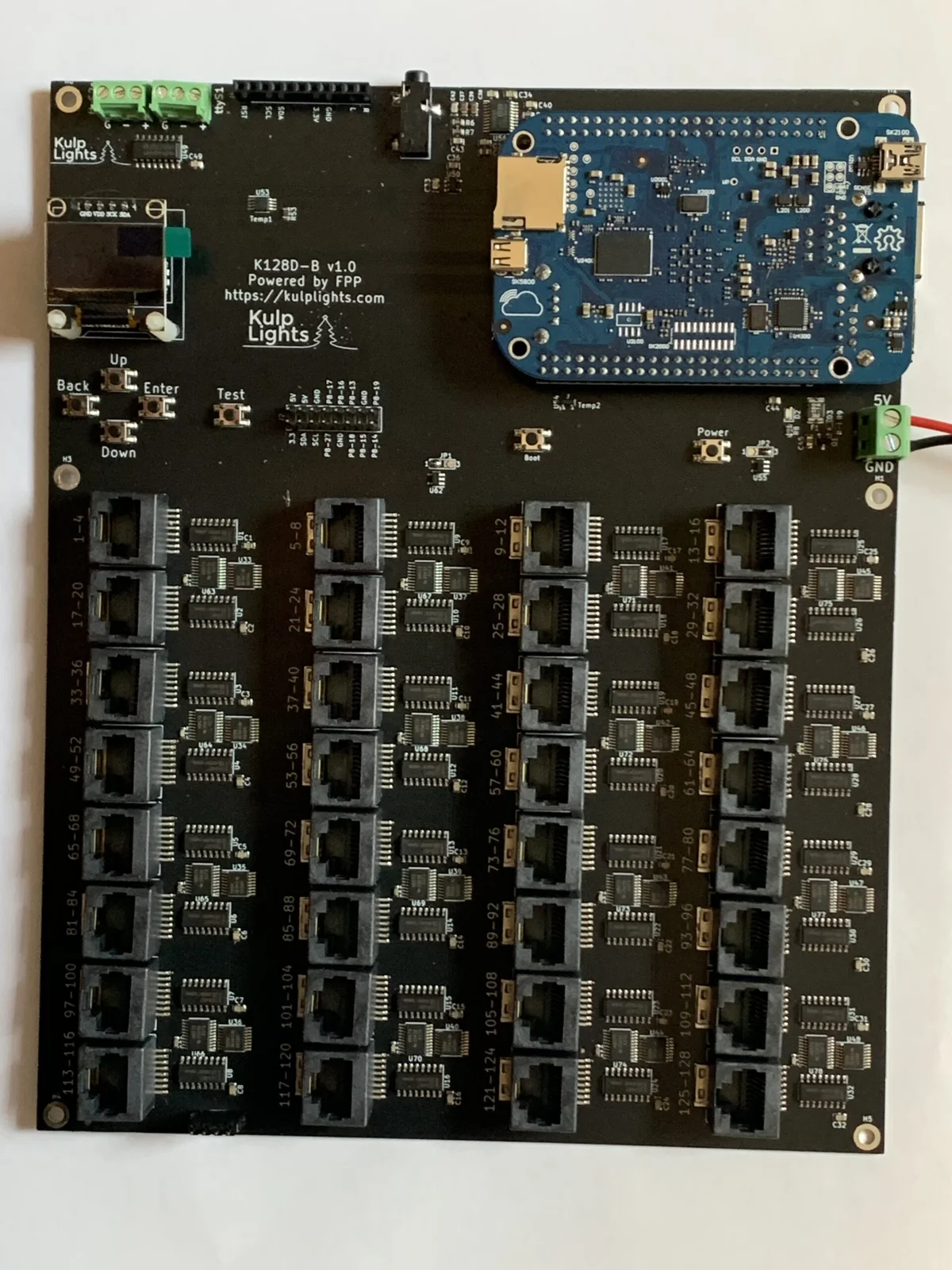
K128D-B
-
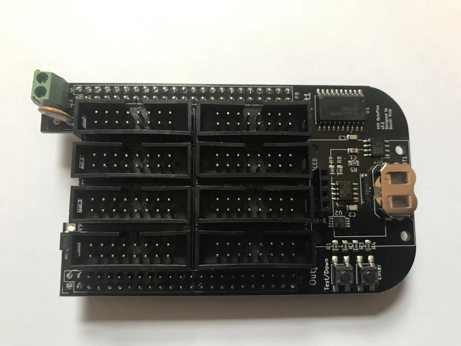
OctoPlus
-
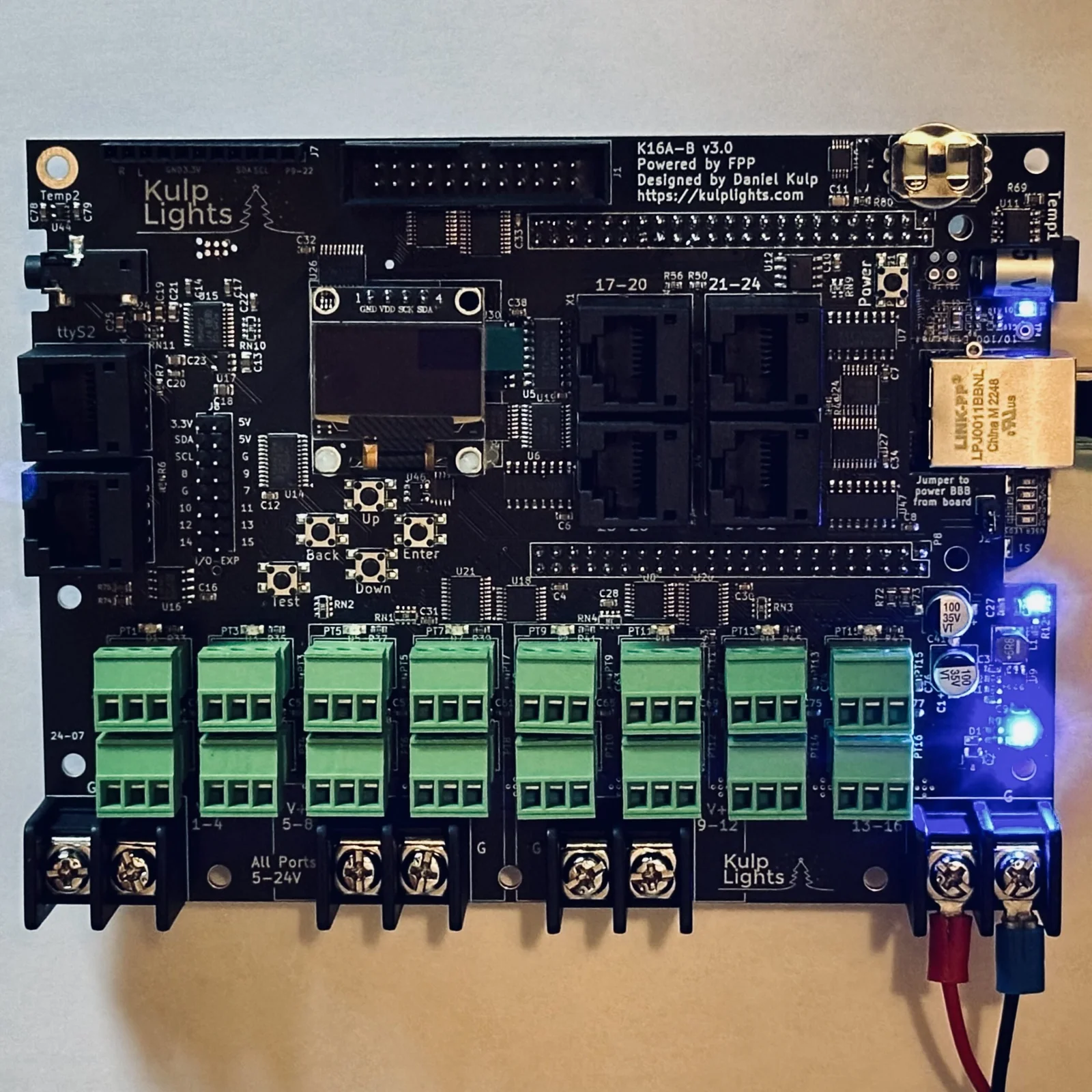
K16A-B (retired)
-
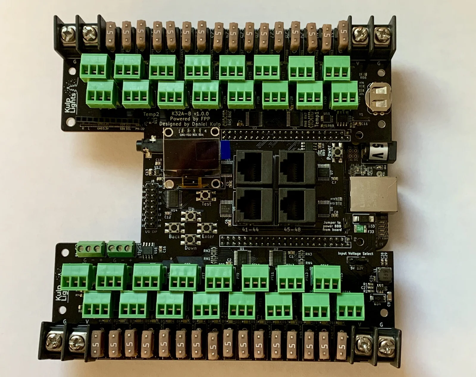
K32A-B (retired)
-
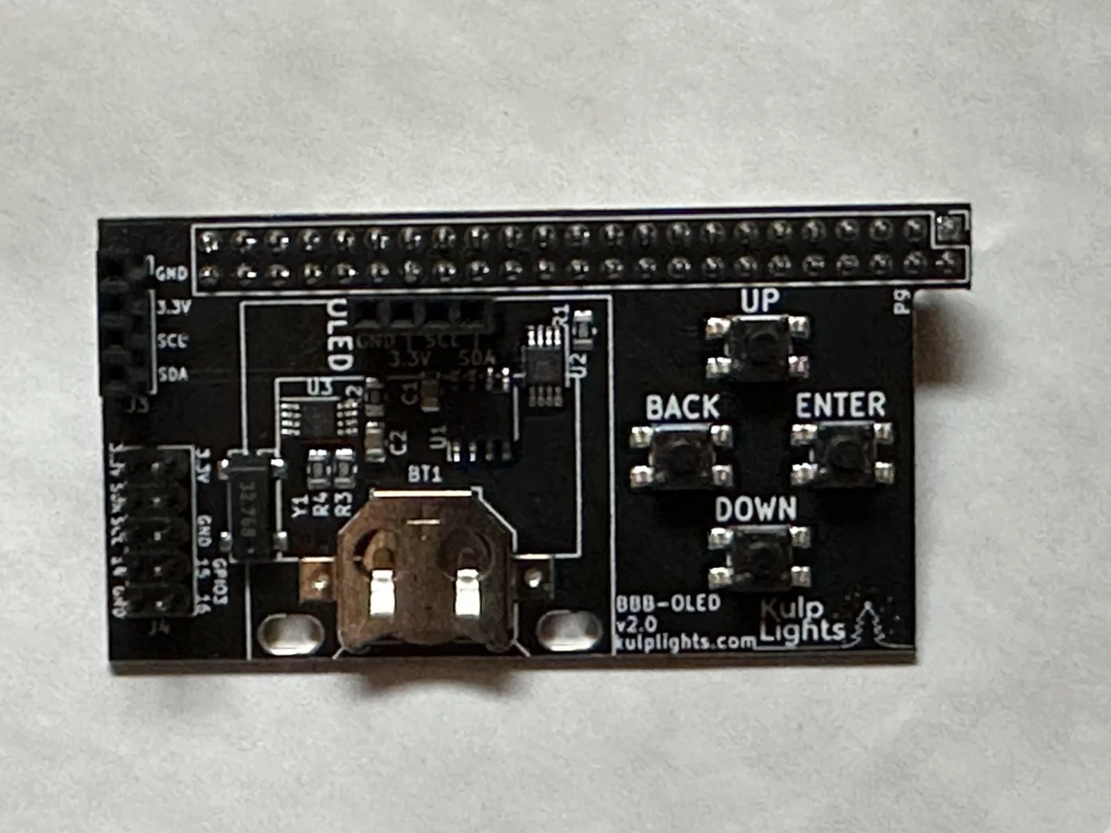
BBB-OLED
-
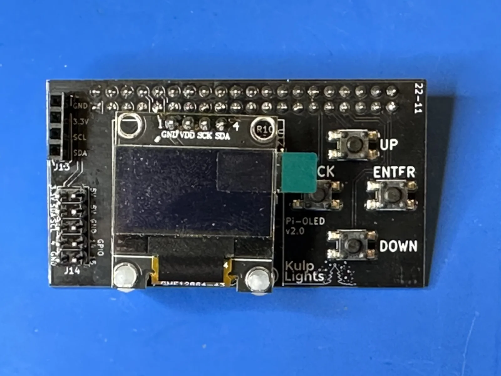
Pi-OLED 2.0
-
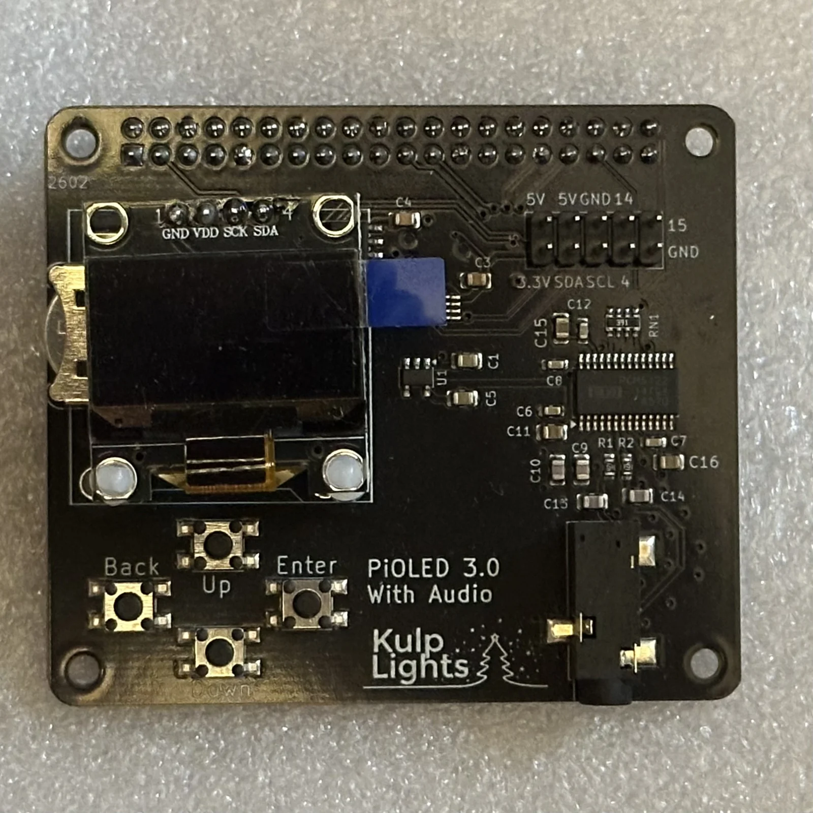
PiOLED 3.0 With Audio
-
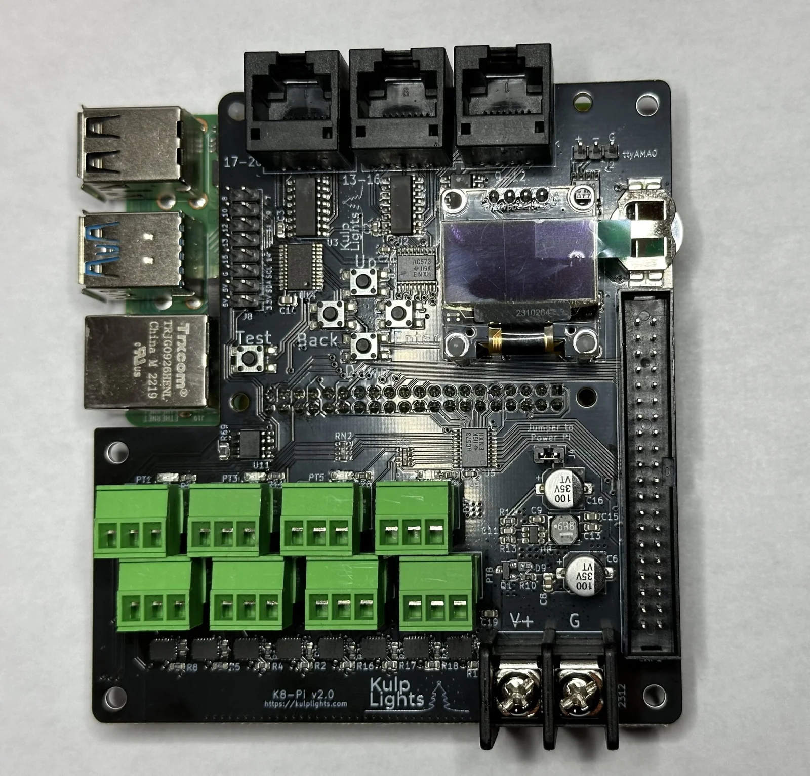
K8-Pi
-
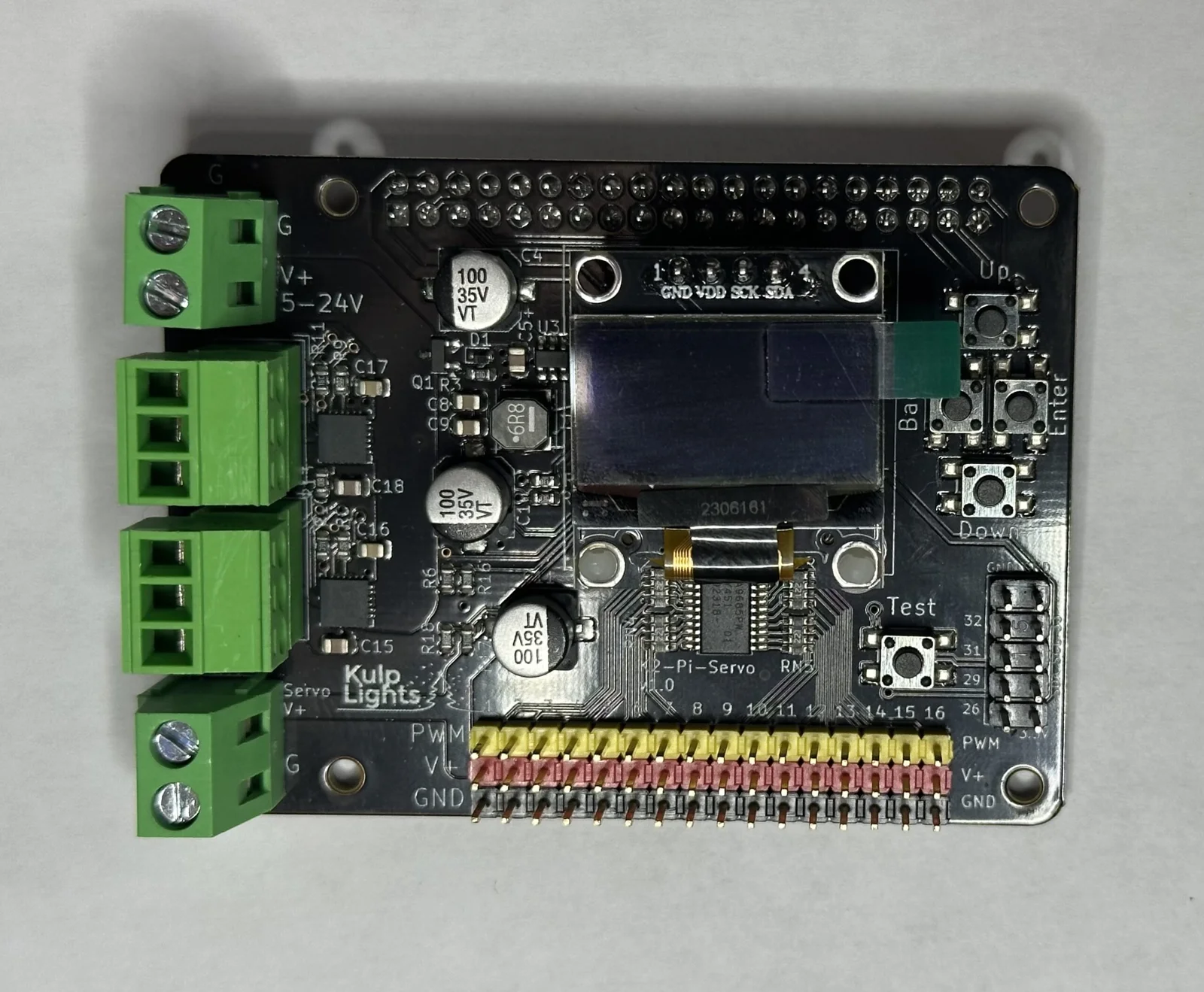
K2-Pi-Servo
-
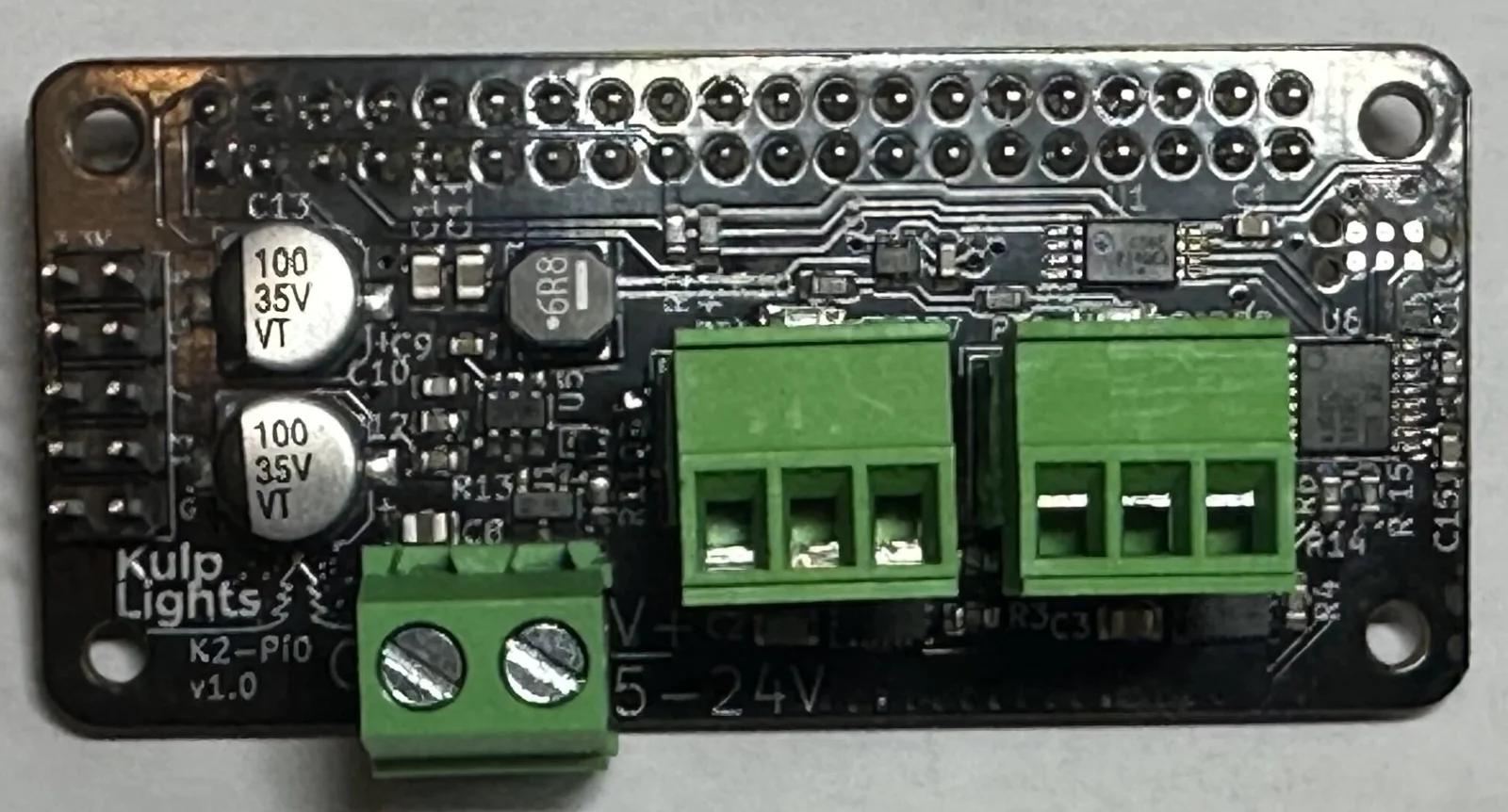
K2-Pi0
For a feature-by-feature comparison, see Boards.
Quick start¶
Work through this list in order. Each step finishes with a check, so if something goes wrong you know which step it was.
What you need¶
- [ ] The controller, with a PocketBeagle 2, BeagleBone Black or Raspberry Pi fitted (see PocketBeagle 2, BeagleBone Black or Raspberry Pi)
- [ ] A microSD card with FPP, unless you have a PB2 Industrial with FPP on eMMC
- [ ] A 5–24 V DC LED power supply matched to your pixels (5 V only for the PocketScrollers, K40D-PB, K64D-B, K128D-B and OctoPlus; 18 V at most for the K8-PB, K4-PB, K8-B, K8-B-Scroller and K8-Pi)
- [ ] An Ethernet cable to your router or show switch. The K8-PB, K4-PB, K40D-PB and PocketScroller v2 have no Ethernet jack, so they also need a USB Ethernet adapter (or a USB Wi-Fi adapter).
- [ ] Pixels with a pigtail wired to a 3-pin plug (or LED panels for the PocketScrollers and OctoPlus)
- [ ] A small flat screwdriver
1. Bench test with one string¶
On the K40D-PB, K64D-B and K128D-B, which have no pixel ports, wire the string to a
differential receiver on the 1-4 jack instead, and power the board from a 5 V supply.
- [ ] Read Safety.
- [ ] Insert the SD card into the PocketBeagle 2, BeagleBone or Pi, unless you are using eMMC.
- [ ] Wire one pixel string to P1: ground in G, data in D, +V in V. Check the pixel voltage matches your supply.
- [ ] Check the supply before connecting it: set its 115V/230V input switch (if it has one) to match your mains, then plug it in and measure the DC output with a multimeter. Unplug it again before wiring. See Check the supply.
- [ ] Wire the supply to the terminal that powers the controller. That's the terminal for ports 1–4 on the K16 and K32, and the right-hand terminal on the K8 boards. On the K8 boards, P1 is fed from the left terminal, so for this test wire both K8 terminals, or use P5 instead. The K8-PB, K4-PB, K8-B, K8-B-Scroller, K8-Pi and K2-Pi0 have a single terminal for everything; on the K2-Pi-Servo, use the top (pixel) terminal. See Power.
- [ ] Plug in the Ethernet cable (on the K8-PB, K4-PB, K40D-PB or PocketScroller v2, through the USB Ethernet adapter).
- [ ] Plug the supply into the mains.
Check: the power LEDs light (on the K8-B and K8-B-Scroller, the green LED above each fuse), and within a minute or two the OLED shows the FPP logo and then the status page with an IP address. The first boot of a new SD card can take a few minutes longer.
2. Connect to FPP¶
- [ ] On a computer on the same network, open a browser to the IP address on the OLED, or to
http://fpp.local. - [ ] Work through FPP's first-time setup: hostname, time zone and so on. See Initial configuration.
Check: the FPP status page shows your board under the cape name, and the header shows the input voltage(s).
3. Light the string¶
- [ ] Press Test on the controller.
Check: the string on P1 cycles red, green and blue. Press Test until the OLED shows Off.
If nothing lights, see Troubleshooting → No pixels light.
4. Configure your show¶
- [ ] In xLights, add the controller as an FPP controller with your board as the model, map your props to its ports, and use Upload Outputs to send the port configuration. See Configuring outputs.
- [ ] Upload sequences and audio with FPP Connect, then build a playlist and a schedule in FPP.
5. Install¶
- [ ] Main Menu → Shutdown (or shut down from FPP), then remove power.
- [ ] Mount the controller in its enclosure. Wire the remaining banks and ports, then the differential receivers.
- [ ] Power up and run the Test patterns again to check every port.
Back up
Once it's working, save a backup from FPP (Status/Control → FPP Backup). See Backup.
Hardware
PocketBeagle 2¶
Every board in this manual is a cape for the BeagleBoard PocketBeagle 2 (PB2). The PB2 is a small computer that runs FPP, and the cape adds the power, outputs and connectors.
PocketBeagle 2 only
These capes do not work with the original PocketBeagle (PocketBeagle 1). The two look alike, but the PocketBeagle 2 has a different processor and pinout. The exceptions are the K4-PB, K40D-PB and PocketScroller v2, which work with either.
Regular or Industrial¶
Kulp Lights sells the boards with or without a PB2 already fitted:
| PocketBeagle 2 | PocketBeagle 2 Industrial | |
|---|---|---|
| Board colour | black | red |
| Memory | 512 MB | 1 GB |
| Storage | microSD card | 64 GB eMMC with FPP pre-installed, microSD optional |
| Temperature range | commercial | −40 to 85 °C |
| Notes | the usual choice | eMMC is about twice as fast as an SD card. Recommended for outdoor or heavily loaded shows. |
Fitting the PocketBeagle 2¶
The PocketBeagle 2 fits the same way round on every board in this manual: its USB-C connector faces the right-hand edge of the board, the edge opposite the buttons and the Exp header. Its P1 header goes into the cape socket marked P1 (the one nearer the Ethernet and USB connectors; on the K8-PB, the upper one), and P2 into P2.
If your board came without a PB2 fitted:
- Disconnect all power.
- On the K8 boards the OLED sits over the PocketBeagle. Unplug it from its 4-pin socket first, removing its standoff screws if fitted.
- Hold the PB2 with its USB-C connector toward the right-hand edge, and line its pins up with both sockets.
- Press it down evenly, rocking gently end to end, until it is fully seated. Don't press on the processor.
- Refit the OLED.
Orientation
A PB2 plugged in backwards, or shifted by a row, can be damaged at power-up. Before you power on, check that the USB-C faces the right-hand edge and that no pins are left over at either end.
Storage: SD card or eMMC¶
- Regular PB2: FPP runs from a microSD card. Use a good-quality card of 16–32 GB (A1/A2, U3). Cheap or counterfeit cards are the most common cause of strange problems. You can buy a card with FPP already installed, or write the PocketBeagle 2 image yourself. See Getting the FPP software.
- PB2 Industrial: FPP is pre-installed on the internal eMMC, so no SD card is needed.
- A microSD extender lets you reach the card slot when the board is in an enclosure.
SD card in a PB2 Industrial¶
A PB2 Industrial always starts from its eMMC, but the bootloader there checks for a valid SD card first and boots from the card if it finds one. So:
- Don't leave an old FPP card in the slot of an Industrial board. It will boot the card, not the eMMC.
- To run a different FPP version or a clean install for a while, just insert a card with FPP on it. Take the card out to go back to the eMMC.
Re-flashing the eMMC¶
To put a fresh copy of FPP on the eMMC, for example to start clean or to recover a broken install:
- Write the PocketBeagle 2 FPP image to an SD card. See Getting the FPP software.
- Insert the card and power up. The board boots from the card.
- In FPP, go to Status/Control → FPP Settings → Storage. Under Flash FPP to Another Device,
find the eMMC (
/dev/mmcblk0) and choose:- Create for a clean install. Your media, sequences and settings are left behind.
- Copy to bring your media, sequences and settings along.
- Wait for it to finish. This can take a while. Then power off, remove the SD card, and power up again from the eMMC.
If the board won't boot at all
If the eMMC's bootloader is damaged, the board can't find the SD card on its own. Hold the PocketBeagle 2's boot button while you apply power to force it to boot from the SD card, then re-flash as above. This is very rarely needed.
You don't need to re-flash to update FPP. FPP and OS updates work in place on the eMMC; see Updating. Re-flashing is only for a clean start or recovery.
The PocketBeagle 2's buttons¶
The PocketBeagle 2 has two small buttons of its own, side by side, separate from the buttons on the cape. They aren't labelled on the board:
| Button | Where | What it does |
|---|---|---|
| Power | the one nearest the board edge and the PocketBeagle's LEDs | Holding it down turns the PocketBeagle 2 off. Don't hold it by accident; to turn off cleanly, use FPP's Shutdown instead. |
| Boot | the one beside it, further from the edge | Only read at power-on. Hold it while you apply power to change where the board boots from (below). |
What the boot button does depends on the model:
| Normal power-on | Boot button held at power-on | |
|---|---|---|
| PocketBeagle 2 Industrial | boots from the eMMC. The bootloader there then switches to an SD card if a valid one is inserted. | boots straight from the SD card, skipping the eMMC. Use this to recover a damaged eMMC. |
| PocketBeagle 2 (regular) | boots from the SD card | also boots from the SD card. The button only changes the fallback the chip tries if the card can't be read, so it has no practical use. |
Using the boot button as an input¶
The boot button only affects booting at power-on, so once FPP is running you can use it as a spare
push button. Starting with FPP 10.4, it appears in FPP's GPIO Inputs as BOOT. Set it up
like any other input to start a playlist, run a command or trigger an effect. See
GPIO Inputs in the FPP manual.
Pressing it while the controller is running is safe: it doesn't reboot or change anything until the next power-on.
Powering¶
The PB2 is powered from the cape, through its power terminal (see Power).
USB-C
Don't use the PB2's USB-C port to power the controller. USB-C powers only the PocketBeagle 2 itself, not the cape's Ethernet, USB ports or outputs. You can still connect it to a computer for setup (USB tethering), except on the K40D-PB, where that can damage the board.
BeagleBone Black¶
The K8-B, K8-B-Scroller, K64D-B, K128D-B and OctoPlus, and the retired K16A-B and K32A-B, are capes for the BeagleBone Black (BBB). The BBB is a small computer that runs FPP, and the cape adds the power, outputs and connectors. FPP drives the outputs from the BBB's two PRUs, small real-time processors beside the main CPU.
Which BeagleBones work¶
| Board | Works? | Notes |
|---|---|---|
| BeagleBone Black | ✔ | the usual choice |
| BeagleBone Black Industrial | ✔ | the same as the BeagleBone Black, with a wider temperature rating |
| BeagleBone Black Wireless | ✔ | Wi-Fi instead of Ethernet |
| BeagleBone Green | ✔ | no barrel jack (it's powered from the cape anyway) |
| SanCloud BeagleBone Enhanced | ✔ | on the OctoPlus, output 5 doesn't work properly |
| BeagleBone Green Wireless | ✘ | not compatible |
| PocketBeagle, PocketBeagle 2, BeagleBone AI | ✘ | different boards. See PocketBeagle 2. |
Kulp Lights sells these boards with or without a BeagleBone Black (or Green) already fitted, and with or without an SD card with FPP on it.
Fitting the BeagleBone¶
The cape connects to the BeagleBone's two 46-pin headers, P8 and P9. How they fit together depends on the board:
- K8-B, K8-B-Scroller and OctoPlus: the cape plugs on top of the BeagleBone. The BeagleBone's Ethernet jack sits in the notch cut out of the cape's edge, so the cape only fits one way round.
- K64D-B and K128D-B: these capes are much bigger, so the BeagleBone plugs upside down onto the cape, with its Ethernet jack over the notch in the cape's right-hand edge. Its microSD slot then faces up, and its USB-A port is still usable.
If your board came without a BeagleBone fitted:
- Disconnect all power.
- Line the BeagleBone's Ethernet jack up with the notch in the cape, and both rows of header pins with both sockets.
- Press evenly along both headers, rocking gently end to end, until the two boards are fully together.
Check before you power on
A cape that is shifted by a row, or fitted the wrong way round, can damage both boards. Check that every pin is in its socket and that none are left over at either end.
Storage: run FPP from an SD card¶
Run FPP from a microSD card in the BeagleBone. Use a good-quality card of 16–32 GB (A1/A2, U3). Cheap or counterfeit cards are the most common cause of strange problems. You can buy a card with FPP already installed, or write the BeagleBone Black image yourself. See Getting the FPP software. Use FPP 9.5 or later; the current release is best.
The BeagleBone also has built-in eMMC storage, but on most boards it is only 4 GB, too small to hold a show's media comfortably, so we recommend the SD card. (BeagleBone Blacks made since late 2025 have 16 GB of eMMC. FPP's Status/Control → FPP Settings → Storage page can copy FPP to it.)
Booting from the SD card¶
BeagleBones made since about 2019 boot from an SD card on their own: insert the card and power up.
Older boards boot whatever is on their eMMC instead. To boot one of those from the SD card, hold the Boot button while you apply power, and keep holding it until the BeagleBone's LEDs start flashing. The K64D-B and K128D-B have a Boot button on the cape for this. On the other boards, use the BeagleBone's own Boot button, next to its USB-A port.
Powering¶
The BeagleBone is powered from the cape: the cape's power terminal feeds the BeagleBone through its header pins (see Power).
Don't power the BeagleBone a second way
- Don't plug a supply into the BeagleBone's barrel jack while the cape is powering it. The two supplies end up tied together. (The K8-B and K8-B-Scroller have a jumper that lets you power the BeagleBone from its barrel jack instead; see their pages.)
- Don't connect the BeagleBone's USB port to a computer (USB tethering) while the cape is powered. Set the controller up over the network instead.
Power button¶
Each cape has a Power button wired to the BeagleBone's own power button, which is hard to reach once a cape is fitted:
- When FPP is running, a short press shuts the BeagleBone down cleanly, the same as FPP's Shutdown.
- After a shutdown, the BeagleBone stays off while the cape is still powered. Press Power to start it again, or switch the supply off and on.
- Holding it down for several seconds forces the BeagleBone off. Use that only if it has hung.
Network and USB¶
- Ethernet: the BeagleBone's own 10/100 Ethernet jack. The BeagleBone Black Wireless has Wi-Fi instead.
- USB: the BeagleBone has one USB-A port, for a USB sound card, Wi-Fi adapter or USB storage.
- Status LEDs: the BeagleBone's four blue LEDs show it booting and running.
Raspberry Pi¶
The K8-Pi, K2-Pi-Servo and K2-Pi0 are hats for the Raspberry Pi. The Pi runs FPP, and the hat adds the power, outputs and connectors.
Which Raspberry Pis work¶
| Board | Raspberry Pi |
|---|---|
| K8-Pi, K2-Pi-Servo | Pi 3 B+, Pi 4 or Pi 5. The hat's mounting holes match these Pis. |
| K2-Pi0 | Pi Zero 2 W, the board it is designed for. It also works on an original Pi Zero W and on the bigger Pis, but see the warning on its board page. |
Kulp Lights sells the boards with or without a Pi, and with or without an SD card with FPP on it.
Fitting the hat¶
The hat has a 40-pin socket on its underside that plugs onto the Pi's GPIO header.
- Disconnect all power.
- Screw M2.5 standoffs, nylon or metal, into the Pi's four mounting holes.
- Line the socket up with all 40 of the Pi's header pins, and press the hat down evenly until it is fully seated on the header and resting on the standoffs.
- Fix the hat to the standoffs with M2.5 screws.
Check before you power on
A hat that is shifted by a row or a column of pins can damage the Pi. Check that every pin is in the socket and none are left over. The standoffs keep the hat from bending down onto the Pi's USB and Ethernet ports; don't leave them out.
The hat sits close over the Pi, so a tall heatsink or fan on the Pi may not fit underneath it. Use a low-profile cooler.
Storage¶
FPP runs from a microSD card in the Pi. Use a good-quality card of 16–32 GB (A1/A2, U3), and the Raspberry Pi FPP image. See Getting the FPP software. Use FPP 10 or later; the current release is best.
Powering¶
The hat powers the Pi: its own regulator turns the supply on the power terminal into 5 V and feeds it to the Pi through the GPIO header.
Don't power the Pi a second way
- Don't plug a supply into the Pi's own USB power socket while the hat is powered. The two supplies end up tied together. (The K8-Pi has a jumper that lets you power the Pi from its own supply instead; see its page.)
- Don't connect the Pi's USB to a computer (USB tethering) while the hat is powered. Set the controller up over the network instead.
Using a 5 V supply
The hats' 5 V regulator can't quite hold 5 V when its input is only 5 V, so the Pi may report under-voltage. If you power one from a 5 V supply, turn the supply's output up to about 5.3 V (most LED supplies have an adjustment screw).
There is no power button on the hats. To turn off, use FPP's Shutdown, then switch off the supply.
Pixel outputs on a Pi¶
FPP drives the pixel ports through the Pi's display output, with its DPIPixels output:
- Each string can have up to 1600 pixels. The frame rate is set by the longest string: about 40 fps at 800 pixels and 20 fps at 1600, and faster for shorter strings.
- That variable frame rate arrived in FPP 10. FPP 9.5 runs only at 20 or 40 fps.
- Smart receivers on the K8-Pi's differential ports work in v1 or v2 mode only.
- The Pi's own audio output still works alongside the pixel outputs.
Network¶
The Pi 3 B+, Pi 4 and Pi 5 have built-in Ethernet and Wi-Fi. The Pi Zero 2 W has Wi-Fi only (2.4 GHz); set it up with FPP's Wi-Fi hotspot.
Power¶
Banks¶
The local pixel ports are grouped in banks of four. Each bank gets its power from one power input terminal. Every port in a bank receives that terminal's voltage, so a bank must be wired to a supply that matches the pixels on all four of its ports.
- Each bank can run its own voltage, so 5 V, 12 V and 24 V pixels can share one controller as long as they are on different banks.
- All grounds (G/V−) are connected together on the board.
- The differential ports carry data only. Strings on differential receivers are powered at the receiver.
The terminals are marked on the board V+ 5-24V and G/V− (V+ 5-18V and G on the K8-PB, V+ and GND on the K4-PB, K8-B and K8-B-Scroller, V+ and G on the Pi boards). Each board page shows which terminal feeds which ports.
| Board | Power terminals | Bank size | Terminal that also powers the controller |
|---|---|---|---|
| K8-Pro, K8-Max | 2 | 4 ports | the right-hand terminal (ports 5–8) |
| K8-PB | 1 (5–18 V) | all 8 ports | the only terminal |
| K4-PB | 1 (5 or 12 V, 18 V max) | all 4 ports | the only terminal |
| K40D-PB | 1 (5 V only) | — (differential only) | the only terminal |
| K16, K16-Pro, K16-Max | 4 | 4 ports | V1, upper left (ports 1–4) |
| K32, K32-Pro, K32-Max | 8 | 4 ports | V1, top left (ports 1–4) |
| PocketScroller v2, v3 and -16 | 1 (5 V only) | — | the only terminal |
| K8-B, K8-B-Scroller | 1 (5–18 V) | all 8 ports | the only terminal |
| K64D-B, K128D-B, OctoPlus | 1 (5 V only) | — | the only terminal |
| K8-Pi | 1 (5–18 V) | all 8 ports | the only terminal |
| K16A-B | 2 (v1, v2) or 4 (v3) | 8 or 4 ports | the right-hand terminal |
| K32A-B | 4 | 8 ports | the bottom-right terminal |
| K2-Pi0 | 1 (5–24 V) | both ports | the only terminal |
| K2-Pi-Servo | 2: pixels (5–24 V) and servos | both pixel ports | the top (pixel) terminal |
One terminal also runs the controller
The PocketBeagle 2 or BeagleBone, network, USB, OLED and all of the controller's logic run from one specific power terminal (the last column above). If that terminal has no power, the controller won't boot, even with every other bank powered. The other terminals power only their own pixel ports.
On the PocketBeagle 2 pixel controllers, a blue LED next to that terminal lights when it has power, and a second blue LED shows that the controller's internal 5 V supply is running.
Voltage¶
- K8, K16 and K32 boards: each terminal accepts 5 V to 24 V DC (as printed next to the terminal). Use a regulated 5 V, 12 V or 24 V LED power supply. Do not go above 24 V; there is no extra headroom for 28 V or 36 V supplies.
- K8-PB and K4-PB: one terminal, 5 V to 18 V DC (5 or 12 V supplies), for the controller and all the ports. No 24 V. See the K8-PB and K4-PB pages.
- K40D-PB: 5 V DC only, for the controller alone, from a supply rated 4–5 A. Its strings are powered at the receivers.
- PocketScroller v2, v3 and -16: 5 V DC only. See their board pages.
- K8-B and K8-B-Scroller: one terminal, 5 V to 18 V DC, for the controller and all the ports. No 24 V.
- K8-Pi: one terminal, 5 V to 18 V DC, for the Pi and all the ports. No 24 V.
- K2-Pi-Servo and K2-Pi0: 5 V to 24 V DC for the Pi and the pixel ports. The K2-Pi-Servo's servos have their own terminal, typically 5–6 V.
- Raspberry Pi boards on 5 V: turn the supply up to about 5.3 V; see Raspberry Pi → Powering.
- K64D-B, K128D-B and OctoPlus: 5 V DC only, for the controller alone (3 A or more for the K64D-B, 4 A or more for the K128D-B). Their strings are powered at the receivers, and the OctoPlus's panels from their own supply.
- A 5 V supply on the logic terminal is fine. The controller's internal 5 V regulator passes it straight through (about 4.96 V out from 5.0 V in), so 5 V-only setups need no separate supply.
Reverse polarity¶
On the K8, K16 and K32 boards each power input has an ideal diode in series. If a supply is wired backwards, that bank simply stays off; nothing on the controller is damaged. Fix the wiring and the bank will come up.
The K8-PB and K4-PB are not protected this way: a reversed supply can damage them. On the K8-B and K8-B-Scroller the BeagleBone and the logic are protected, but a reversed supply goes straight through the fuses to the pixel ports. The K64D-B isn't protected either. On the Raspberry Pi boards the Pi and the logic are protected, but the pixel ports aren't. Check the polarity before you power up. Pixels have no such protection; see Safety.
Voltage readings in FPP¶
FPP shows each input voltage in its status bar and on the OLED status pages (VIN1, VIN2, …). The terminals aren't numbered on the board, so each board page has a map of which VIN reading belongs to which terminal. On the K32 boards, for example, VIN3 is the right-hand top terminal (ports 17–20).
Choosing power supplies¶
- Use regulated, constant-voltage LED power supplies (often sold as 350 W 5 V/12 V/24 V "Meanwell-style" units). Constant-current LED drivers are not suitable.
- Size the supply for the pixels, not the controller. The controller itself needs only a few watts.
- Pixel current depends on brightness and colour. A full-white string draws its full rated current; most shows average far less. Common practice is to size each supply for about 60–80 % of the pixels' full-white load, and to cap brightness in FPP or xLights if needed.
- One supply can feed several banks, as long as each wire run is sized for its current.
Check the supply before you connect it¶
Do this for every supply, new or used, before you wire it to the controller:
- Set the AC input switch. Many supplies have a small slide switch, often red, marked 115V / 230V (or 110V / 220V). Set it to match your mains: 115 V in North America, 230 V in most of Europe, Asia and Australia. A supply set to 115 V and plugged into 230 V mains is destroyed at once, and can catch fire. One set to 230 V on 115 V mains won't start or gives a low output. Supplies without the switch accept either.
- Measure the output. With nothing connected to the DC side, plug the supply in and measure across its V+ and V− (COM) terminals with a multimeter. Check it reads the voltage your pixels need (5, 12 or 24 V) and that + and − are where you expect. If it is slightly off, most supplies have a V.ADJ trim pot next to the terminals.
- Unplug the supply and wait for its LED to go out before you wire it to the controller.
Wire size¶
Use copper wire sized for the highest current that wire can carry. That means the bank's total for supply-to-terminal wires, and the port fuse or eFuse rating for pixel leads.
| Current (continuous) | Minimum wire |
|---|---|
| up to 5 A (one port) | 18 AWG (0.75 mm²) |
| up to 10 A | 16 AWG (1.5 mm²) |
| up to 15 A | 14 AWG (2.5 mm²) |
| up to 20 A (a fused bank: 4 ports × 5 A) | 12 AWG (4 mm²) |
| up to 24 A (a Max bank: 4 ports × 6 A) | 10 AWG (6 mm²) |
Bank power wiring
Use 12 AWG or 10 AWG wire from the power supply to each bank terminal. The terminals are rated 30 A each, which is more than a bank can draw: 20 A on a fused bank, 24 A on a Max bank.
Keep supply-to-controller runs short. For long runs, go up a wire size so the voltage drop stays small.
Port protection: fuses and eFuses¶
Every local pixel port has its own overcurrent protection. What kind depends on the model:
| Model | Port protection | Per-port power control | Per-port current reading |
|---|---|---|---|
| K16, K32 | 5 A mini-blade fuse | no | no |
| K8-Pro, K16-Pro, K32-Pro | 5 A mini-blade fuse | yes, per bank of 41 | only from Falcon V5 receivers |
| K8-Max, K16-Max, K32-Max | eFuse, about 6 A | yes, per port | yes, every port |
| K8-PB, K4-PB | eFuse, about 5.2 A | yes, per port | yes, every port |
| K8-B, K8-B-Scroller | 5 A mini-blade fuse | no | no |
| K8-Pi (v2.x) | eFuse, about 5.2 A | yes, per port | yes, every port |
| K2-Pi-Servo, K2-Pi0 | eFuse, about 6 A | yes, per port | yes, every port |
Mini-blade fuses (K16, K32, the Pro boards, K8-B and K8-B-Scroller)¶
- Each port has an automotive mini-blade fuse (ATM/APM style). All of them are 5 A, on every board. Spares are sold as a 10-pack and at any auto-parts store.
- Each port has a green LED. It lights when that port has power, which means the bank is powered (and switched on, on Pro boards) and the fuse is intact. A dark LED on a powered bank usually means a blown fuse.
- Never fit a fuse larger than 5 A. Find the cause of a blown fuse (a short in the pigtail, a pinched wire, water in a connector) before you replace it.
eFuses (Max boards, K8-PB, K4-PB and the Pi boards)¶
The Max boards, the K8-PB and the K4-PB replace each port's fuse with an eFuse, an electronic fuse that FPP can switch on and off and read back.
- Trip point: about 6 A per port (5.6–6.4 A) on the Max boards, the K2-Pi-Servo and the K2-Pi0, and about 5.2 A on the K8-PB, K4-PB and K8-Pi. A hard short trips it at once.
- When it trips the port turns off and stays off (it latches). The port's LED goes dark, FPP shows a warning, and the Port Status page marks the port as tripped.
- To reset: fix the cause, then click the port's red icon on Status/Control → Port Status. Power-cycling the controller also resets it.
- FPP can retry tripped ports automatically. See eFuse auto-retry.
- FPP reads every port's current continuously. See Current monitoring.
Power injection on Max boards
If you inject power at the far end of a string, use the same power supply that feeds that port's bank. A different supply at even a slightly higher voltage pushes current backwards into the port. The eFuse treats that as a fault and switches the port off.
Bank switching (Pro boards)¶
On the Pro boards each bank has an electronic power switch that FPP controls. All four ports of a bank switch together. The K8-Pro has had bank switching since v4.0. The K16-Pro and K32-Pro have it from v4.1; on v4.0 boards every bank is on whenever it has power. The revision is printed next to the model name on the board.
- With FPP's Automatically turn on/off outputs setting on (the default, under Settings → Output), FPP turns bank power off when it has no data to send and back on when a sequence or test starts. That cuts the idle draw of the pixels.
- The port LEDs show the switch state: a bank that is switched off has all four LEDs dark.
- The voltage readings in FPP are taken before the switch, so a switched-off bank still shows its input voltage.
The Max boards do the same thing for each port separately, using the eFuses.
Ports power up on
On every board, the ports and banks come up switched on as soon as power is applied, before FPP has started. FPP then takes over and switches off ports and banks that are unused or idle. Treat every port as live whenever its bank's supply is on.
-
K8-Pro: all revisions. K16-Pro and K32-Pro: v4.1 and later. ↩
Pixel outputs¶
The local pixel ports are labelled P1, P2, … on the board (PT1, PT2, … on the K8-PB and K4-PB). Each is a 3-pin, 3.5 mm pluggable (Phoenix-style) connector, and the plugs come with the board. The plug pulls straight off the board, so you can wire your pigtails at the bench and plug them in on site. Spare plugs, in screw or spring-clamp ("Advanced") styles, are sold as pixel connectors.
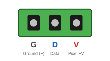
| Pin | Silk | Signal |
|---|---|---|
| 1 | G | Ground (−) |
| 2 | D | Data |
| 3 | V | Pixel power (+), fused, from that port's bank |
The letters G D V are printed next to every port. Check them against your pigtail colours before you power up. Pixel colour codes vary by manufacturer, and a reversed string is usually destroyed at once.
Wiring a pigtail¶
- Strip about 6 mm (¼ in) of each wire. Tin the strands or fit a ferrule.
- Loosen the three screws on the plug and insert the wires: ground in G, data in D, and +V in V.
- Tighten each screw firmly and tug-test each wire.
- With the power off, push the plug fully onto its port.
Wire size
The plugs take wire up to 16 AWG (1.5 mm²). Use 16 or 18 AWG pigtails for strings that draw several amps.
Data signal¶
- The data output is 5 V logic on every board, whatever the pixel voltage. It works directly with WS2811/WS2812-family pixels at 5, 12 and 24 V.
- Each data line has a series resistor at the controller. For long first runs (more than about 5 m / 15 ft to the first pixel), use a null pixel or a differential receiver instead of a long bare data lead.
How many pixels per port?¶
FPP drives up to 800 pixels per port at 40 frames per second on these boards, on the local ports and on each differential string. Plan power injection for anything over a few hundred pixels. A long string needs power at both ends or along its length, not just from the controller.
Smart receivers use some of the 800
When a differential port runs smart receivers, the smart-receiver protocol uses part of that port's pixel time. v2 and V4 cost only a few pixels, but V5 leaves about 725, and v1 loses more with each receiver. See Pixel budget with smart receivers. Receivers in dumb mode cost nothing.
Port numbering¶
FPP's port numbers match the silk: P1 is FPP port 1, and so on. The differential
ports continue the numbering after the local ports. On a K16, for example, the RJ45
marked 17-20 carries FPP ports 17, 18, 19 and 20.
Each board page has a map showing where each port is on the board.
Port LEDs¶
Each local port has a small green LED next to it:
| LED | Meaning |
|---|---|
| On | The port has power. The bank is powered, and the fuse is intact (eFuse not tripped). |
| Off, rest of bank on | Blown fuse (K16/K32/Pro), tripped or disabled eFuse (Max) |
| Off, whole bank off | No power on that bank's terminal, or the bank is switched off (Pro/Max) |
The LED shows power, not data. To check data, run a test pattern.
Differential ports¶
The RJ45 jacks labelled with port ranges (9-12, 17-20, 21-24, …) are
differential pixel ports. Each carries four pixel strings as balanced
(RS-422-style) data over a standard network cable. At the far end, a
differential receiver turns the data back into four ordinary pixel outputs and powers
them from its own supply.
Differential data travels hundreds of feet. Use it to put pixel outputs where the props are, instead of running long pixel leads from the controller.
These are not Ethernet ports
Do not plug the differential ports into a network switch, router or PC. The controller's one real Ethernet port is the metal-shielded jack with built-in LEDs. The differential jacks are all black plastic.
Pinout¶
All differential ports on all boards use the same pinout. The four strings are called
A–D in the order of the label. On a jack labelled 17-20, A is string 17 and D is string 20.
| RJ45 pin | Signal | Cable pair (T568B colours) |
|---|---|---|
| 1 | String A + | orange-white |
| 2 | String A − | orange |
| 3 | String B + | green-white |
| 6 | String B − | green |
| 5 | String C + | blue-white |
| 4 | String C − | blue |
| 7 | String D + | brown-white |
| 8 | String D − | brown |
There is no ground and no power on the cable; all eight wires are data.
Receivers¶
Any receiver that uses the standard four-strings-per-RJ45 differential pinout above will work. That includes the Kulp Lights receivers and Falcon-compatible receivers.
- Smart Receiver SRx1: 4 strings.
- Long-range SRx2 and SRx4.
Smart receivers and chaining¶
Smart receivers can be chained: up to six receivers on one differential port, sharing that port's pixel allocation. Give each receiver in the chain its own position on its selector dial, as described in the receiver's instructions, and turn termination on at the last receiver only. Set the chain up in FPP on the port's row in the Pixel Strings table. See the FPP manual.
Pixel budget with smart receivers¶
FPP drives up to 800 pixels per port at 40 fps. The smart-receiver protocol shares that time with the pixels, so it lowers the budget. How much depends on which protocol the receivers use (set per port in FPP):
| Protocol | Overhead | Does 800 px at 40 fps fit? |
|---|---|---|
| None (dumb receivers) | none | Yes |
| v1 | about 12 / 36 / 66 px for 1 / 2 / 3 receivers, every frame | With 1 receiver only. 3 receivers leave about 757 px. |
| v2 | none for the first receiver, then about 3–4 px for each one after | Yes, up to the 6-receiver maximum (about 17 px for 6) |
| V4 | a config packet of about 25 px on 1 frame in 12 | Just: about 798 px is the safe limit |
| V5 | a status query of up to about 96 px on most frames | No. Keep to about 725 px, or run 800 px at about 36–37 fps |
The budget is per port. All the receivers in a chain share it: output 1 of receivers 1, 2 and 3 together get what's left on that port. An empty receiver position in the middle of a v1/v2 chain also costs one pixel.
V5 costs the most because it is the protocol that reports back (see below): on most frames the controller sends a query and then waits for the receiver to answer. If you don't need the readings, V4 costs far less.
Two-way ports (Pro and Max boards)¶
On the K8-Pro, K8-Max, K16-Pro, K16-Max, K32-Pro and K32-Max the differential ports are bi-directional. Pair 1/2 also carries data back from the receiver. Falcon V5 smart receivers use it to report their eFuse status, current and other readings, and FPP shows them on the Port Status page next to the local ports. Only Falcon V5 receivers report back. Every other receiver works as a normal, send-only receiver on these ports.
On the K16, K32, K8-PB and K40D-PB the differential ports are send-only. Every receiver works, but none can report back.
K8-PB and K40D-PB: no V5
FPP drives the K8-PB and K40D-PB with its BBB48String output, which has no V5 protocol. Set smart receivers on these boards to v1, v2 or V4. A V5 setting falls back to V4.
Cabling tips¶
- Use solid-core Cat5e or Cat6 with factory-made or carefully crimped ends. A bad crimp on one pair kills one string and is hard to find.
- Outdoors, use outdoor-rated (UV/direct-burial) cable and keep the RJ45 ends dry.
- If a receiver has a terminator setting, turn termination on at the last receiver in a chain only.
- Each receiver has a test button and data LEDs. Use them to tell a cable problem from a configuration problem. See the receiver's documentation.
DMX / serial outputs¶
The RJ45 jacks labelled DMX (or DMX1 / DMX2) are RS-485 serial outputs. FPP can drive them as:
- DMX512 (DMX-Open), for floods, moving heads and DMX relay boxes
- Pixelnet
- Renard and LOR (Light-O-Rama) networks
| Board | Serial outputs | FPP name | Pin |
|---|---|---|---|
| K8-Pro, K8-Max, K16, K32 | 1 | DMX |
P2-07 |
| K16-Pro, K16-Max, K32-Pro, K32-Max | 2 | DMX1, DMX2 |
P2-07, P1-08 |
| K8-PB | 1, on a 3-pin header (FPP 10.3 or later) | ttyS2 |
P1-10 |
| K4-PB | 1, on a 3-pin header | ttyS4 |
P2-07 |
| K40D-PB | 1, on a 3-pin pluggable terminal | ttyS4 |
P2-07 |
| PocketScroller v2, v3 and -16 | none | — | — |
| K8-B, K8-B-Scroller | 2, on a 2×3 header | ttyS1, ttyS2 |
P9-24, P9-21 |
| K64D-B, K128D-B | 2, RJ45 with a DMX/LOR switch | ttyS1, ttyS2 |
P9-24, P9-21 |
| OctoPlus | none | — | — |
| K16A-B | 2: 3-pin terminals (v1), RJ45 (v2, v3) | ttyS1, ttyS2 |
P9-24, P9-21 |
| K32A-B | 2, on 3-pin terminals | ttyS1, ttyS2 |
P9-24, P9-21 |
| K8-Pi | 1, on a 3-pin header | ttyAMA0 |
Pi GPIO14 (pin 8) |
| K2-Pi-Servo, K2-Pi0 | none | — | — |
Pinout¶
These are the RJ45 jacks on the K8, K16 and K32 boards. The K8-PB, K4-PB and K40D-PB have a 3-pin header or terminal instead, and the K8-B and K8-B-Scroller a 2×3 header; see their board pages (K8-PB, K4-PB, K40D-PB, K8-B, K8-B-Scroller). The K64D-B and K128D-B jacks use this pinout with their switch set to DMX; set to LOR, they suit LOR networks directly (K64D-B, K128D-B).
The pinout follows the ESTA standard for DMX over RJ45 (ANSI E1.27-2):
| RJ45 pin | Signal | DMX XLR pin |
|---|---|---|
| 1 | Data + | 3 |
| 2 | Data − | 2 |
| 7, 8 | Ground | 1 |
| 3–6 | not connected | — |
To connect fixtures with XLR inputs, use an RJ45-to-XLR DMX adapter wired to this standard.
LOR, Renard and Pixelnet need an adapter
The jack is wired for standard DMX only. To drive Light-O-Rama, Renard or Pixelnet devices, use an adapter cable that takes data + / − (pins 1 and 2) and ground (pins 7 and 8) to the pins that device expects. Don't connect them with a plain network cable.
Notes¶
- These are outputs only. The controller doesn't receive DMX or RDM.
- A 120 Ω termination resistor is fitted permanently at the controller. Put a terminator on the last fixture in the DMX chain.
- Set the outputs up in FPP under Input/Output Setup → Channel Outputs → Other. FPP installs a disabled DMX-Open output on each port. Enable it and set the start channel and channel count. See the FPP manual.
Controls & display¶
Every board has a small OLED display and five buttons: Up, Down, Enter, Back and Test. The K8-PB and K40D-PB have four: Down and Test share one button, marked Down Test (Down/Test on the K40D-PB). On the status page it works as Test; in menus it works as Down. The K4-PB, PocketScroller v2 and OctoPlus have two buttons, Down (which is also Test, as on the K8-PB) and Enter. The K2-Pi0 has no display or buttons. The BeagleBone Black boards also have a Power button (and the K64D-B and K128D-B a Boot button) for the BeagleBone; see BeagleBone Black. From them you can check status, read the IP address, change modes and run test patterns without a computer.
The OLED¶
Every board comes with the OLED fitted. It is a 128×64 I²C display that plugs into a 4-pin socket marked
GND 3.3V SCL SDA. FPP sets it up automatically. If the display is ever blank, check
Status Display under Settings → System in FPP. See the
FPP manual.
- After a while without a button press, the display turns itself off. Any button wakes it.
- If you mount the controller upside down, choose a flipped display type in the same setting.
Status pages¶
The display normally shows the status page: hostname, IP address(es), FPP mode and what is playing. When the board has sensors, press Enter to step through:
- Status: network addresses, mode, playlist and sequence
- Sensors: input voltages (VIN1, VIN2, …), temperature, and on Max boards the current per port. Use Up/Down to scroll.
- Pressing Enter again opens the Main Menu.
Main Menu¶
| Item | What it does |
|---|---|
| FPP Mode | Switch between Player and Remote mode |
| Tethering | Turn FPP's Wi-Fi hotspot to Automatic, On or Off (needs a USB Wi-Fi adapter) |
| Testing | Pick a test pattern (white, red, green, blue, cycles, chases) and optionally run it across MultiSync |
| Reboot / Shutdown | Restart or shut down the PocketBeagle, BeagleBone or Pi cleanly |
| Reset | Factory-reset all FPP settings, or just a part of them (network, outputs, playlists…) |
| About | FPP version, cape and serial number |
| Back | Return to the status page |
Use Up/Down to move, Enter to choose and Back to go back.
Shut down before unplugging
Use Main Menu → Shutdown (or the FPP web UI) before you remove power. Pulling the power while FPP is writing can corrupt the SD card.
Test button¶
Pressing Test on the status page starts a test pattern on every output and steps through the patterns:
Off → R-G-B Cycle → R-G-B-W-N Cycle → R-G-B Chase → R-G-B-W-N Chase → Off
While a test is running, Up slows it down and Down speeds it up. Press Test until the display shows Off to stop.
The test drives every configured port, including the differential ports. It's the quickest way to check wiring before you build a sequence. On boards with switched ports (Pro/Max), FPP powers the ports for the test.
Note
The test uses the pixel counts set in FPP's Pixel Strings page. A fresh board is set to 50 pixels per local port (100 on the BeagleBone Black and Raspberry Pi boards), so on a longer string only the first ones light up until you set the real count.
Status LEDs¶
| LED | Colour | Meaning |
|---|---|---|
| Next to the logic power terminal | blue | That terminal has power |
| Near the power section | blue | The controller's internal 5 V supply is on |
| One per local pixel port | green | The port has power. See Pixel outputs. |
| Ethernet jack | left / right | Link (left) and activity (right). See Network. |
| On the PocketBeagle 2 | various | Boot and activity (see PocketBeagle 2) |
The PocketScrollers and the OctoPlus have no power LEDs; check the OLED and the Ethernet LEDs instead. On the K8-B and K8-B-Scroller the green LED above each fuse lights when the fuse is good, and the K64D-B and K128D-B have one power LED beside their power terminal. On the Raspberry Pi boards the LED by each pixel port lights when the port has power. The K8-PB has no Ethernet jack; its two blue LEDs are on the right-hand edge (see its board page).
Audio¶
| Board | Audio |
|---|---|
| K8-Pro, K8-Max, K16-Pro, K16-Max, K32-Pro, K32-Max | Built-in stereo DAC, 3.5 mm line out, FM transmitter socket |
| K64D-B, K128D-B, K16A-B, K32A-B | Built-in stereo DAC, 3.5 mm line out, FM transmitter socket |
| K16, K32, K8-PB, K4-PB, K40D-PB, PocketScroller v2, v3 and -16, K8-B, K8-B-Scroller, OctoPlus | None built in. Use a USB sound card. |
| K8-Pi, K2-Pi-Servo | The Pi 3 B+ or Pi 4's own audio jack (the Pi 5 has none), or a USB sound card. |
| K2-Pi0 | None (the Pi Zero has no audio output). Use a USB sound card on the Pi's USB port. |
| PiOLED 3.0 With Audio | Built-in PCM5122 stereo DAC, 3.5 mm line out. See Pi-OLED. |
Line output¶
The built-in audio uses a PCM5102A 24-bit DAC on the board, so it has no USB jitter or ground noise.
- 3.5 mm stereo jack (tip = left, ring = right, sleeve = ground).
- Line level (about 2 V RMS at full volume). It's meant for an amplifier, powered speakers or an FM transmitter's line input. It is not a headphone amplifier, though headphones will work at low volume.
- FPP lists it as the CapeAudio sound card and selects it automatically. Volume is set in FPP's status page or with the volume commands. See the FPP manual.
FM transmitter socket¶
Boards with built-in audio also have an 11-pin socket marked
RST SCL SDA 3.3V G L R for the plug-in
Si4713 FM transmitter. The module receives
the same audio as the line output, and FPP's FM transmitter plugin controls it over I²C.
| Pin | Signal |
|---|---|
| 1 | RST (module reset) |
| 3 | SCL |
| 4 | SDA |
| 7 | 3.3 V |
| 8 | GND |
| 10 | Left audio |
| 11 | Right audio |
| 2, 5, 6, 9 | not connected |
Warning
Broadcasting on FM is regulated. Check the power and frequency rules where you live.
USB sound cards¶
On boards without built-in audio, plug a USB sound card into a USB-A port and select it in FPP under Settings → Audio/Video.
Network, USB & clock¶
Ethernet¶
Every PocketBeagle 2 board except the K8-PB, K4-PB, K40D-PB and PocketScroller v2 has one Gigabit Ethernet jack, the RJ45 with built-in LEDs. It connects to the PocketBeagle 2 over USB 2.0, so real throughput is roughly 300 Mb/s. That is far more than a show needs, even with hundreds of E1.31 universes.
- Plug it into your show network switch or router.
- Out of the box FPP uses DHCP. The IP address appears on the OLED.
- K8-PB, K4-PB, K40D-PB and PocketScroller v2: there's no Ethernet jack. Plug a USB Ethernet adapter (or a USB Wi-Fi adapter) into its USB-A port.
- BeagleBone Black boards (K8-B, K8-B-Scroller, K64D-B, K128D-B, OctoPlus) use the BeagleBone's own 10/100 Ethernet jack, which is plenty for a show. A BeagleBone Black Wireless uses Wi-Fi instead. See BeagleBone Black.
- Raspberry Pi boards use the Pi's own Ethernet and Wi-Fi. The Pi Zero 2 W under a K2-Pi0 has Wi-Fi only. See Raspberry Pi.
- For networking topics (static IPs, show networks, reaching receivers or controllers behind FPP), see the FPP manual: Network · Networking overview · Proxies.
Only one RJ45 is Ethernet
The DMX and differential RJ45 jacks look the same but are not network ports. Never plug them into a switch or PC.
The Ethernet jack has two built-in LEDs. Left and right are as seen in the photo at the top of each board page, with the board laid flat and the Ethernet jack on the top edge:
| LED | Meaning |
|---|---|
| Left | Link. On when the cable is connected to a working switch or router port. |
| Right | Activity. Flashes as network traffic passes. |
If the link LED stays off, check the cable and the switch port before anything else.
Wi-Fi¶
The PocketBeagle 2 and the BeagleBone Black have no built-in Wi-Fi (the BeagleBone Black Wireless does). Plug an FPP-supported USB Wi-Fi adapter into a USB-A port to get:
- Wi-Fi as a second network
- FPP's hotspot (tethering) mode, for setup in the field
See the FPP manual's hardware list for supported adapters.
USB tethering¶
You can also set the controller up over a USB cable, with no network at all. Connect the PocketBeagle 2's USB-C port to a computer, wait for FPP to start, then browse to:
- 192.168.7.2 on Windows
- 192.168.6.2 on macOS or Linux
Over USB-C alone, only the PocketBeagle 2 itself is powered: the cape's Ethernet, USB ports and outputs stay off until the cape has its own power. That's fine for configuring FPP. On the K8, K16 and K32 boards, the K8-PB, the K4-PB, and all the PocketScrollers it's also safe to keep the USB cable connected while the cape has its own power.
Not on the K40D-PB, or with a PocketBeagle 1
Never connect the PocketBeagle's USB port to a computer on a K40D-PB, or on a K4-PB or PocketScroller v2 fitted with an original PocketBeagle 1. It can permanently damage the board. Use a USB network adapter instead. A K4-PB or PocketScroller v2 with a PocketBeagle 2 is fine.
BeagleBone Black and Raspberry Pi boards: not while the cape is powered
On the BeagleBone Black and Raspberry Pi boards, never connect the BeagleBone's or Pi's USB port to a computer while the cape is powered. See BeagleBone Black and Raspberry Pi.
USB ports¶
| Board | USB-A host ports |
|---|---|
| K8-Pro, K8-Max, K16-Pro, K16-Max, K32-Pro, K32-Max, PocketScroller v3, PocketScroller-16 | 3 (one vertical, plus a stacked pair) |
| K16, K32, K8-PB, K4-PB, K40D-PB, PocketScroller v2 | 1 |
| K8-B, K8-B-Scroller, K64D-B, K128D-B, OctoPlus | 1, on the BeagleBone |
| K8-Pi, K2-Pi-Servo | the Pi's own (2 to 4) |
| K2-Pi0 | the Pi Zero's micro-USB data port, through an OTG adapter |
On the PocketBeagle 2 boards each port has its own current-limited power switch, about 0.5 A. That's plenty for Wi-Fi adapters, sound cards and USB flash drives. Use a powered hub for anything hungrier, such as a USB hard drive.
K16 and K32: use the included USB extension cable
The K16's and K32's single USB-A port needs the USB extension cable that comes with the board. Plug the cable into the port, then plug your Wi-Fi adapter or other device into the cable, not straight into the port. Keep the cable with the controller.
Real-time clock (RTC)¶
Every board except the K4-PB, PocketScroller v2, K2-Pi-Servo and K2-Pi0 has a battery-backed real-time clock (NXP PCF85263, PCF85363 or PCF8523, depending on the board), so schedules start at the right time even with no internet for NTP. The K4-PB, PocketScroller v2, K2-Pi-Servo and K2-Pi0 have no clock, so set up NTP on them.
- Every board takes a CR1220 3 V coin cell. On the K8 boards the holder is on the underside of the board. On the K64D-B, K128D-B and OctoPlus it is under the OLED: unplug the OLED to reach it.
- FPP sets the RTC up automatically from the cape. The RTC setting is hidden because there is nothing to choose.
- Set the time zone and NTP in FPP under Settings → Time.
Temperature¶
A temperature sensor on the board (a TMP1075 on most PocketBeagle 2 boards) reports the board
temperature. Some boards, such as the K8-B, K64D-B and K128D-B, have a second one (Temp2). FPP shows it with the
other sensors. Boards with a fan header use it to run the fan
(see Expansion header & fan).
Expansion header & fan¶
Expansion header (Exp)¶
The Pro and Max boards, the PocketScroller v3 and the PocketScroller-16 have a 2×6, 2.54 mm pin header
marked Exp. It brings out the cape's I²C bus and eight general-purpose I/O pins,
which FPP names Exp.1 to Exp.8.
Use them for:
- Buttons and switches. In FPP, set up GPIO Inputs to start playlists, run commands or trigger effects. See the FPP manual.
- Outputs to relays (through a driver or relay module), such as a "show running" light.
- I²C accessories such as extra sensors.
The pin positions differ between boards, so check the numbers printed next to the header.
The K8-PB has a different, 24-pin expansion port that drives 16 extra pixel strings through a Falcon F16v4-style expansion board. See its board page.
| Pin | Signal | Pin | Signal |
|---|---|---|---|
| 1 | 3.3 V | 2 | Exp.1 |
| 3 | SDA | 4 | Exp.2 |
| 5 | SCL | 6 | Exp.3 |
| 7 | Exp.4 | 8 | Exp.5 |
| 9 | GND | 10 | Exp.6 |
| 11 | Exp.7 | 12 | Exp.8 |
| Pin | Signal | Pin | Signal |
|---|---|---|---|
| 1 | 3.3 V | 2 | Exp.8 |
| 3 | SDA | 4 | Exp.7 |
| 5 | SCL | 6 | Exp.6 |
| 7 | Exp.4 | 8 | Exp.5 |
| 9 | GND | 10 | Exp.3 |
| 11 | Exp.1 | 12 | Exp.2 |
Electrical limits
The Exp pins come from an I²C I/O expander. They are 3.3 V only, and they pull up weakly and can only sink current. Use them with switches to ground, or to drive a transistor or an opto-isolated relay module. Do not connect 5 V or 12 V signals, and don't drive LEDs or relays directly.
The K16 and K32 have no expansion header.
Fan¶
The Pro and Max boards have a 4-pin 5 V PWM fan header marked Fan 5V. It's the standard PC-fan layout:
| Pin | Signal |
|---|---|
| 1 | GND |
| 2 | +5 V |
| 3 | Tach (speed sense) |
| 4 | PWM (speed control) |
Use a 5 V 4-pin PWM fan. 12 V PC fans won't spin properly. FPP controls the fan from the board temperature sensor:
| Board temperature | Fan speed |
|---|---|
| below 40 °C | off |
| 40 °C | about 30 % |
| 50 °C | about 60 % |
| 60 °C and above | 100 % |
A fan is optional. Most installations don't need one, but it helps in a closed enclosure in direct sun, or with Max boards running many ports near their limit.
Boards from revision v4.1 also read the fan's tach signal, so FPP can monitor the fan's speed. Earlier boards control the fan the same way but can't tell whether it is spinning.
Boards
Boards¶
All of the boards use the same building blocks, so each board page is short and links to the shared Hardware chapters for details.
PocketBeagle 2 boards¶
Pixel controllers¶
| K8-Pro | K8-Max | K16 | K16-Pro | K16-Max | K32 | K32-Pro | K32-Max | |
|---|---|---|---|---|---|---|---|---|
| Local pixel ports | 8 | 8 | 16 | 16 | 16 | 32 | 32 | 32 |
| Differential ports (strings) | 4 (16) | 4 (16) | 4 (16) | 8 (32) | 8 (32) | 4 (16) | 8 (32) | 8 (32) |
| Total strings | 24 | 24 | 32 | 48 | 48 | 48 | 64 | 64 |
| Port protection | fuse | eFuse | fuse | fuse | eFuse | fuse | fuse | eFuse |
| Port power control | bank | port | — | bank† | port | — | bank† | port |
| Per-port current reading | — | ✔ | — | — | ✔ | — | — | ✔ |
| Two-way differential (Falcon V5 receivers) | ✔ | ✔ | — | ✔ | ✔ | — | ✔ | ✔ |
| Power inputs (5–24 V) | 2 | 2 | 4 | 4 | 4 | 8 | 8 | 8 |
| DMX / serial outputs | 1 | 1 | 1 | 2 | 2 | 1 | 2 | 2 |
| Built-in audio + FM socket | ✔ | ✔ | — | ✔ | ✔ | — | ✔ | ✔ |
| USB-A ports | 3 | 3 | 1 | 3 | 3 | 1 | 3 | 3 |
| Fan header | ✔ | ✔ | — | ✔ | ✔ | — | ✔ | ✔ |
| Expansion header | ✔ | ✔ | — | ✔ | ✔ | — | ✔ | ✔ |
| Size (mm) | 103 × 129 | 103 × 129 | 169 × 139 | 169 × 139 | 169 × 139 | 169 × 203 | 169 × 203 | 169 × 203 |
Fuse = 5 A mini-blade per port. eFuse = electronic fuse, about 6 A per port, switchable and monitored. †Bank switching on the K16-Pro and K32-Pro starts at board revision v4.1.
Which model line?¶
- Base (K16, K32): the most outputs for the money. Fused ports and send-only differential.
- Pro: adds two-way differential for Falcon V5 receivers, audio, a second DMX output, three USB ports, a fan header and expansion I/O. Bank power switching (K8-Pro, and K16-Pro/K32-Pro from v4.1).
- Max: everything in Pro, plus an eFuse on every port. FPP can switch each port and read its current, and a short is cut in microseconds and reported in FPP instead of blowing a fuse.
Compact controllers: K8-PB, K4-PB and K40D-PB¶
| K8-PB | K4-PB | K40D-PB | |
|---|---|---|---|
| Local pixel ports | 8, eFused | 4, eFused | — |
| Differential ports (strings) | 3 (12) | — | 10 (40) |
| Expansion port | 16 strings | — | — |
| Total strings | 36 | 4 | 40 |
| Power input | 5–18 V | 5 or 12 V | 5 V only |
| DMX / serial | 3-pin header | 3-pin header | 3-pin terminal |
| Ethernet | none (USB adapter) | none (USB adapter) | none (USB adapter) |
| Real-time clock | ✔ | — | ✔ |
| Size (mm) | 74 × 97 | 71 × 67 | 83 × 99 |
All three use an older output driver (BBB48String), so their differential ports are send-only with no Falcon V5 support. The K8-PB's expansion port drives 16 strings through a Falcon F16v4-style expansion board, and the K4-PB fits a small TA-200 enclosure. See the K8-PB, K4-PB and K40D-PB pages.
LED panels¶
| PocketScroller v2 | PocketScroller v3 | PocketScroller-16 | |
|---|---|---|---|
| HUB75 outputs | 6 | 8 | 16 |
| Power | 5 V only | 5 V only | 5 V only |
| Ethernet | none (USB adapter) | ✔ | ✔ |
| USB-A | 1 | 3 | 3 |
| Real-time clock | — | ✔ | ✔ |
| Expansion header | — | ✔ | ✔ |
| Size (mm) | 61 × 73 | 122 × 101 | 122 × 144 |
| Minimum FPP | 9.5 on PB2 (10+ recommended) | 9.0 | 10.0 |
BeagleBone Black boards¶
| K8-B | K8-B-Scroller | K64D-B | K128D-B | OctoPlus | |
|---|---|---|---|---|---|
| Local pixel ports | 8, fused | 8, fused | — | — | — |
| Differential ports (strings) | 3 (12) | 1 (4) | 16 (64) | 32 (128) | — |
| Expansion port | 16 strings | — | — | — | — |
| HUB75 panel outputs | — | 3 | — | — | 8 |
| Total strings | 36 | 12 | 64 | 128 | — |
| Power input | 5–18 V | 5–18 V | 5 V only | 5 V only | 5 V only |
| DMX / serial | 2 (header) | 2 (header) | 2 (RJ45, DMX/LOR) | 2 (RJ45, DMX/LOR) | — |
| Built-in audio + FM socket | — | — | ✔ | ✔ | — |
| Real-time clock | ✔ | ✔ | ✔ | ✔ | ✔ |
| Size (mm) | 86 × 109 | 86 × 109 | 182 × 160 | 182 × 225 | 55 × 99 |
All five are capes for the BeagleBone Black, which provides the Ethernet and USB port. Their differential ports are send-only: smart receivers work in v1, v2 or V4 mode. See BeagleBone Black.
Retired BeagleBone Black boards¶
| K16A-B | K32A-B | |
|---|---|---|
| Local pixel ports | 16 | 32, fused |
| Port protection | fuses (v1), eFuses (v2, v3) | 5 A fuse |
| Differential ports (strings) | 4 (16) | 4 (16) |
| Expansion port | 16 strings | — |
| Total strings | 48 | 48 |
| Power terminals | 2 (v1, v2) or 4 (v3) | 4 |
| DMX / serial | 2 | 2 |
| Built-in audio + FM socket | ✔ | ✔ |
| Size (mm) | 150 × 114 | 150 × 150 |
No longer sold, but still widely used. See the K16A-B and K32A-B pages.
Raspberry Pi boards¶
| K8-Pi | K2-Pi-Servo | K2-Pi0 | |
|---|---|---|---|
| Local pixel ports | 8, eFused | 2, eFused | 2, eFused |
| Differential ports (strings) | 3 (12) | — | — |
| Expansion port | 16 strings | — | — |
| Servo outputs | — | 16 | — |
| Total strings | 36 | 2 | 2 |
| Power input | 5–18 V | 5–24 V (+ servo supply) | 5–24 V |
| DMX / serial | 1 (header) | — | — |
| Display & buttons | ✔ | ✔ | — |
| Real-time clock | ✔ | — | — |
| Raspberry Pi | 3 B+, 4, 5 | 3 B+, 4, 5 | Zero 2 W |
| Size (mm) | 98 × 106 | 76 × 56 | 65 × 30 |
All three are hats for the Raspberry Pi, which provides the network and USB ports. FPP drives their pixel ports with its DPIPixels output: up to 1600 pixels per string, with smart receivers in v1 or v2 mode. See Raspberry Pi.
Displays & add-ons¶
The BBB-OLED and Pi-OLED add a status display, menu buttons, a real-time clock and a temperature sensor to a BeagleBone Black or Raspberry Pi running FPP, with no outputs of their own. The PiOLED 3.0 also adds a high-quality line-level audio output.
All boards¶
All of them run FPP. The boards in the PocketBeagle 2 section need a PocketBeagle 2; the K4-PB, K40D-PB and PocketScroller v2 also work with the original PocketBeagle 1. See PocketBeagle 2, BeagleBone Black and Raspberry Pi.
PocketBeagle 2
K8-Pro¶
8 fused pixel ports, 4 two-way differential ports, audio and DMX.
K8-Pro with a PocketBeagle 2 fitted. Photos may show an earlier board revision.
This page describes revision v4.1.0 (printed on the board as K8-Pro v4.1.0). Differences in earlier revisions are listed under Board revisions.
Specifications¶
| K8-Pro | |
|---|---|
| Local pixel ports | 8 (P1–P8), 3-pin 3.5 mm pluggable, plugs included |
| Port protection | 5 A mini-blade fuse per port |
| Power switching | per bank of 4 (FPP-controlled) |
| Current monitoring | from Falcon V5 receivers only |
| Differential ports | 4 × RJ45 = 16 strings (9–24), two-way (pair 1/2) |
| Total strings | 24 |
| Power inputs | 2 terminals rated 30 A, 5–24 V DC, one bank of 4 ports each |
| DMX / serial | 1 (DMX), RS-485 transmit |
| Audio | PCM5102A DAC, 3.5 mm line out, FM transmitter socket |
| Ethernet | 1 × Gigabit (USB-attached) |
| USB-A | 3 |
| Display & buttons | 128×64 OLED, Up / Down / Enter / Back / Test |
| Real-time clock | yes, CR1220 backup cell |
| Fan header | 5 V 4-pin PWM, temperature-controlled; speed monitoring on v4.1 and later |
| Expansion header | 2×6: I²C + 8 GPIO (Exp.1–Exp.8) |
| Size | 103.0 × 129.4 mm (4.06 × 5.09 in), 6 mounting holes, 3.0 mm |
| Requires | PocketBeagle 2 (not PocketBeagle 1), FPP 9.0 or later |
Board map¶
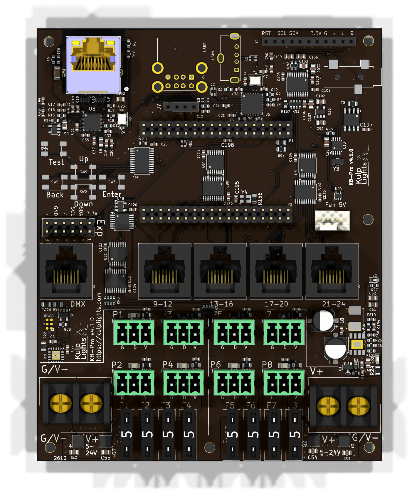
Power terminals¶
| Terminal | Feeds | FPP reading | Also powers the controller? |
|---|---|---|---|
| Left (bottom edge) | P1–P4 | VIN1 | no |
| Right (bottom edge) | P5–P8 | VIN2 | yes |
The blue LED beside the right terminal lights when it has power. The right terminal must be powered for the controller to boot.
See Power for supply sizing, wire size and safety.
Pixel ports¶
The eight pixel ports are in two rows across the lower part of the board:
| Top row | P1 | P3 | P5 | P7 |
| Bottom row | P2 | P4 | P6 | P8 |
Each port is G D V (ground, data, +V), as printed beside it. See Pixel outputs.
Fuses¶
Every local port has a 5 A mini-blade fuse next to it. If a port's green LED is dark while the rest of its bank is lit, check that port's fuse first. Never fit a fuse larger than 5 A. See Power → Fuses.
On the K8-Pro all eight fuses sit in one row along the bottom edge, between the two power terminals.
Bank switching¶
Each bank of four ports has an electronic power switch that FPP controls, so FPP can turn pixel power off when nothing is playing. See Power → Bank switching.
Differential ports¶
9-12 · 13-16 · 17-20 · 21-24
Each jack carries four strings, numbered as printed above it. They are two-way: Falcon V5 smart receivers report their eFuse status and current back over pair 1/2. Other receivers work as send-only. See Differential ports.
Other connectors¶
| Connector | Marking | Details |
|---|---|---|
| Ethernet | (RJ45 with LEDs) | Network |
| DMX | DMX |
DMX / serial |
| USB-A | — | 3 ports, USB |
| OLED | GND 3.3V SCL SDA |
Controls & display |
| Audio out | 3.5 mm jack | Audio |
| FM transmitter | RST SCL SDA 3.3V G L R |
Audio |
| Fan | Fan 5V |
Fan |
| Expansion | Exp |
Expansion header |
| RTC battery | coin-cell holder (underside) | Clock |
FPP setup¶
When FPP detects the K8-Pro it sets itself up automatically. It enables the K8-Pro pixel-string layout, the sensors (input voltages, temperature), the audio output and a disabled DMX output. Out of the box each local port is set to 50 WS2811 pixels at 50 % brightness. Set the real counts and start channels from xLights or the FPP Pixel Strings page. See Configuring outputs.
Board revisions¶
The revision is printed on the board next to the model name. FPP also shows it as the Hardware Version under Help → About → Cape Info.
| Revision | Changes |
|---|---|
| v4.0 | Fused ports with bank switching. Fan speed control. |
| v4.1 | Adds fan speed monitoring. |
Dimensions & mounting¶
- 103.05 × 129.39 mm (4.06 × 5.09 in), 6 plated mounting holes, 3.0 mm, for M2.5 (or #4) screws and standoffs.
- The mounting holes are connected to ground.
- Use nylon or metal standoffs at least 6 mm (¼ in) tall, so nothing on the underside touches the enclosure.
- Mounting drawing: PDF. It is shared by the K8-Pro and K8-Max, which have the same outline and holes.
K8-Max¶
8 eFused pixel ports with per-port current monitoring, 4 two-way differential ports, audio and DMX.
K8-Max with a PocketBeagle 2 fitted. Photos may show an earlier board revision.
This page describes revision v4.1.0 (printed on the board as K8-Max v4.1.0). Differences in earlier revisions are listed under Board revisions.
Specifications¶
| K8-Max | |
|---|---|
| Local pixel ports | 8 (P1–P8), 3-pin 3.5 mm pluggable, plugs included |
| Port protection | eFuse per port, about 6 A, latching |
| Power switching | per port (FPP-controlled) |
| Current monitoring | every local port, plus Falcon V5 receivers |
| Differential ports | 4 × RJ45 = 16 strings (9–24), two-way (pair 1/2) |
| Total strings | 24 |
| Power inputs | 2 terminals rated 30 A, 5–24 V DC, one bank of 4 ports each |
| DMX / serial | 1 (DMX), RS-485 transmit |
| Audio | PCM5102A DAC, 3.5 mm line out, FM transmitter socket |
| Ethernet | 1 × Gigabit (USB-attached) |
| USB-A | 3 |
| Display & buttons | 128×64 OLED, Up / Down / Enter / Back / Test |
| Real-time clock | yes, CR1220 backup cell |
| Fan header | 5 V 4-pin PWM, temperature-controlled; speed monitoring on v4.1 and later |
| Expansion header | 2×6: I²C + 8 GPIO (Exp.1–Exp.8) |
| Size | 103.0 × 129.4 mm (4.06 × 5.09 in), 6 mounting holes, 3.0 mm |
| Requires | PocketBeagle 2 (not PocketBeagle 1), FPP 9.0 or later |
Board map¶
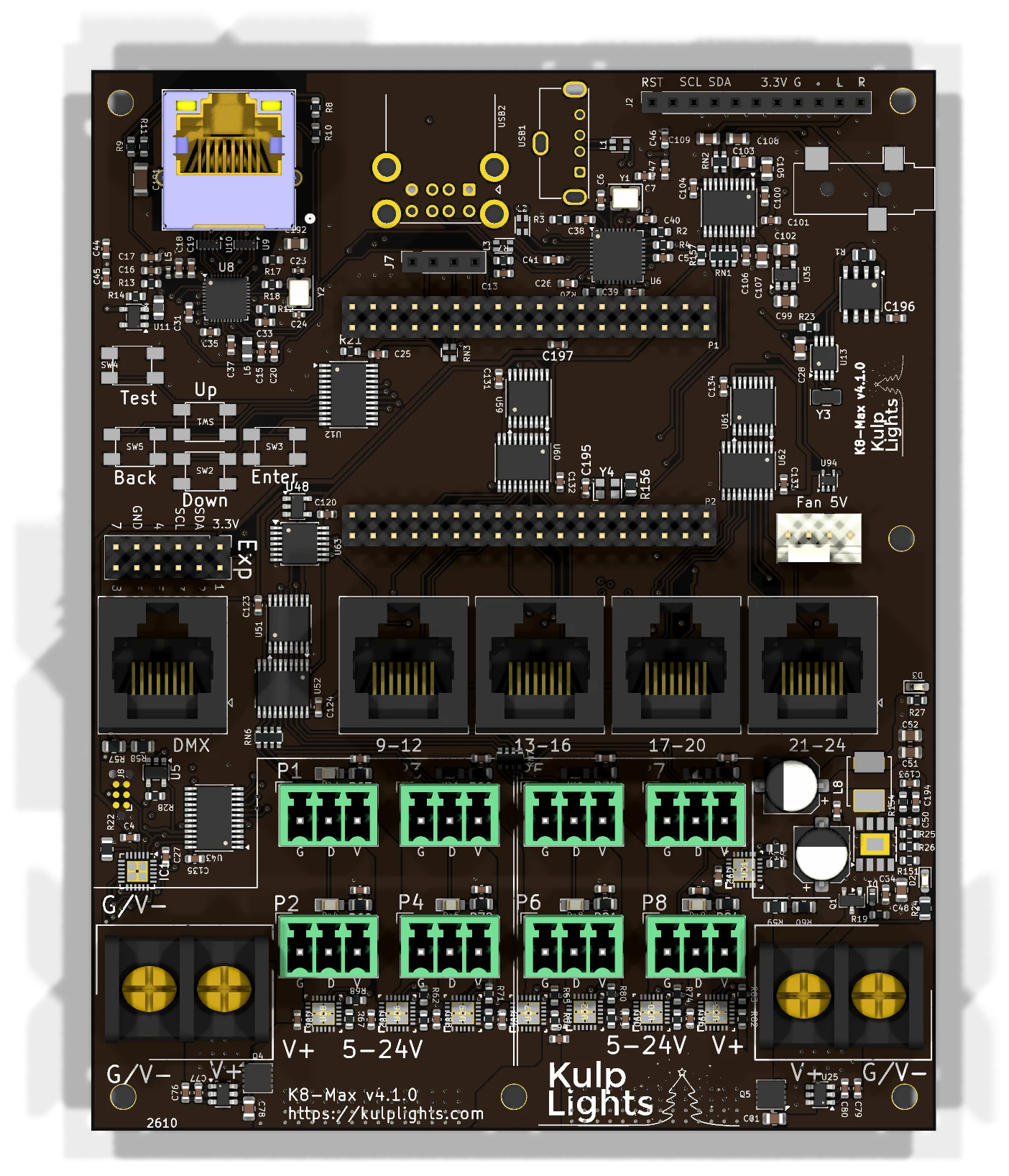
Power terminals¶
| Terminal | Feeds | FPP reading | Also powers the controller? |
|---|---|---|---|
| Left (bottom edge) | P1–P4 | VIN1 | no |
| Right (bottom edge) | P5–P8 | VIN2 | yes |
The blue LED beside the right terminal lights when it has power. The right terminal must be powered for the controller to boot.
See Power for supply sizing, wire size and safety.
Pixel ports¶
The eight pixel ports are in two rows across the lower part of the board:
| Top row | P1 | P3 | P5 | P7 |
| Bottom row | P2 | P4 | P6 | P8 |
Each port is G D V (ground, data, +V), as printed beside it. See Pixel outputs.
eFuses and current monitoring¶
Every local port has its own eFuse (about 6 A), and FPP reads every port's current. FPP turns each port on and off as needed. A tripped port shows a red icon on Status/Control → Port Status; click it to reset the port once the fault is fixed. See Power → eFuses and Current monitoring.
Differential ports¶
9-12 · 13-16 · 17-20 · 21-24
Each jack carries four strings, numbered as printed above it. They are two-way: Falcon V5 smart receivers report their eFuse status and current back over pair 1/2. Other receivers work as send-only. See Differential ports.
Other connectors¶
| Connector | Marking | Details |
|---|---|---|
| Ethernet | (RJ45 with LEDs) | Network |
| DMX | DMX |
DMX / serial |
| USB-A | — | 3 ports, USB |
| OLED | GND 3.3V SCL SDA |
Controls & display |
| Audio out | 3.5 mm jack | Audio |
| FM transmitter | RST SCL SDA 3.3V G L R |
Audio |
| Fan | Fan 5V |
Fan |
| Expansion | Exp |
Expansion header |
| RTC battery | coin-cell holder (underside) | Clock |
FPP setup¶
When FPP detects the K8-Max it sets itself up automatically. It enables the K8-Max pixel-string layout, the sensors (input voltages, port currents, temperature), the audio output and a disabled DMX output. Out of the box each local port is set to 50 WS2811 pixels at 50 % brightness. Set the real counts and start channels from xLights or the FPP Pixel Strings page. See Configuring outputs.
Board revisions¶
The revision is printed on the board next to the model name. FPP also shows it as the Hardware Version under Help → About → Cape Info.
| Revision | Changes |
|---|---|
| v4.0 | eFused ports with current monitoring. Fan speed control. |
| v4.1 | Adds fan speed monitoring. |
Dimensions & mounting¶
- 103.05 × 129.39 mm (4.06 × 5.09 in), 6 plated mounting holes, 3.0 mm, for M2.5 (or #4) screws and standoffs.
- The mounting holes are connected to ground.
- Use nylon or metal standoffs at least 6 mm (¼ in) tall, so nothing on the underside touches the enclosure.
- Mounting drawing: PDF. It is shared by the K8-Pro and K8-Max, which have the same outline and holes.
K8-PB¶
A compact controller: 8 eFused pixel ports with per-port current monitoring, 3 differential ports and an expansion port for 16 more strings: 36 strings in all, on a 74 × 97 mm board.
K8-PB with a PocketBeagle 2 fitted.
This page describes revision v2.6.0 (printed on the board as K8-PB v2.6.0). The
PocketBeagle 2 K8-PBs are v2.5 and v2.6; see Board revisions for the
one difference.
How the K8-PB differs from the other boards
- No Ethernet on the board. Plug a USB Ethernet adapter or an FPP-supported USB Wi-Fi adapter into its USB-A port. You need one of them to set it up.
- One power terminal, 5–18 V. It powers the controller and all eight ports, so all of them run at the same voltage. Don't use 24 V supplies.
- DMX is a 3-pin header, not an RJ45 jack.
- The expansion port drives 16 more strings through a Falcon F16v4-style expansion board.
- The differential ports are send-only. FPP drives this board with its BBB48String output, which doesn't support Falcon V5 smart receivers (V4 and earlier work).
Specifications¶
| K8-PB | |
|---|---|
| Local pixel ports | 8 (PT1–PT8), 3-pin 3.5 mm pluggable, plugs included |
| Port protection | eFuse per port, about 5.2 A |
| Power switching | per port (FPP-controlled) |
| Current monitoring | every local port |
| Differential ports | 3 × RJ45 = 12 strings (9–20), send-only |
| Expansion port | 24-pin (2×12) header, 16 strings (21–36), for a Falcon F16v4-style expansion board |
| Total strings | 36 |
| Power input | 1 terminal, 5–18 V DC, powers the controller and all 8 ports |
| DMX / serial | 1, RS-485 transmit, 3-pin 2.54 mm header (ttyS2). Needs FPP 10.3 or later. |
| Audio | none built in. Use a USB sound card. |
| Ethernet | none. Use a USB Ethernet or Wi-Fi adapter. |
| USB-A | 1 |
| Display & buttons | 128×64 OLED, Up / Enter / Back / Down-Test |
| Real-time clock | yes, CR1220 backup cell |
| Temperature sensor | yes |
| Fan header | none |
| Size | 73.7 × 97.2 mm (2.90 × 3.83 in), 4 mounting holes, 3.2 mm |
| Requires | PocketBeagle 2. The PocketBeagle 2 K8-PB does not work with a PocketBeagle 1. |
Board map¶
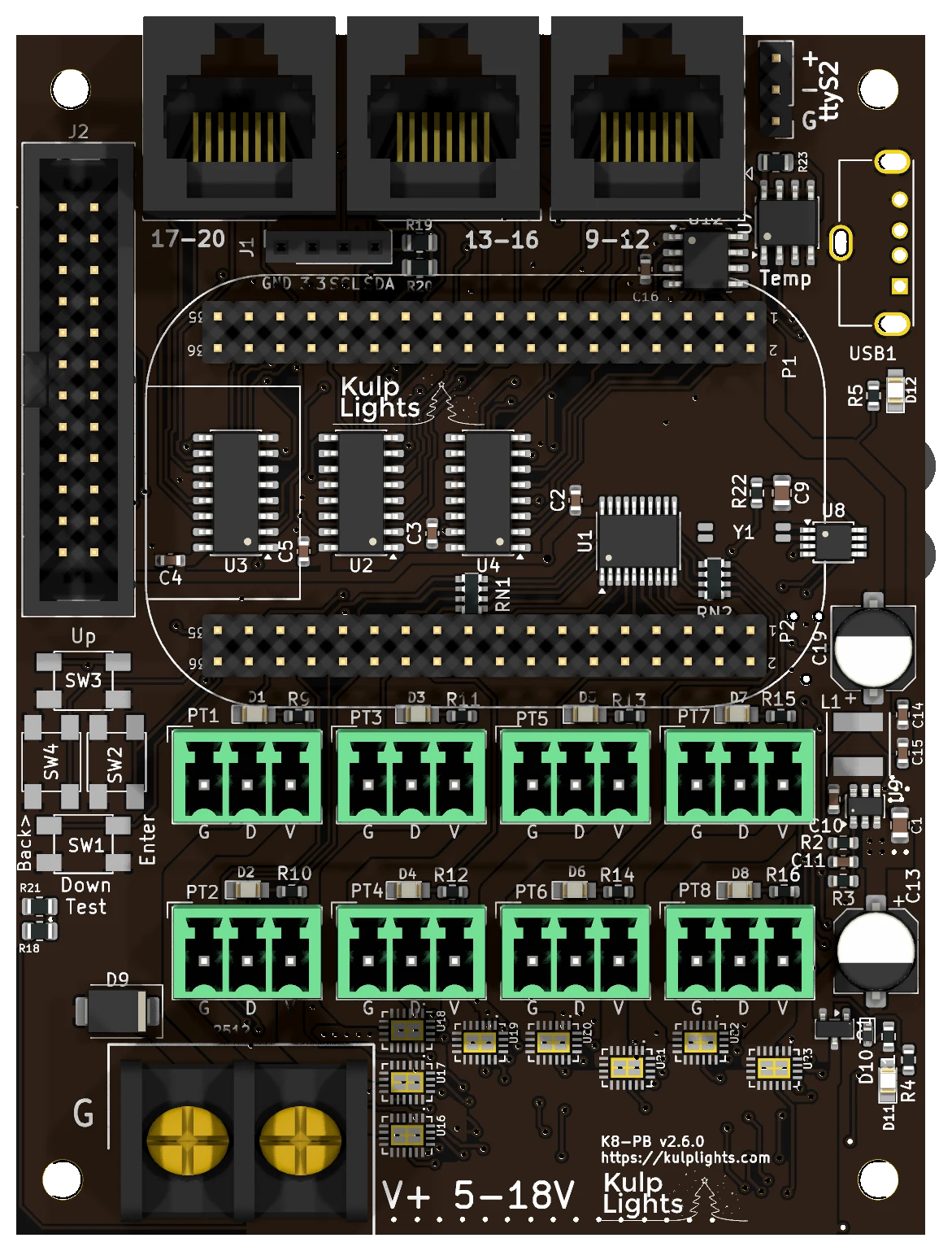
Power terminal¶
The K8-PB has one power terminal, at the bottom left, marked G (left screw) and V+ 5-18V (right screw). It powers the PocketBeagle 2, the USB port and all of the logic, and every pixel port. FPP shows its voltage as VIN.
- Because every port shares this supply, all eight local strings must be the same voltage: 5 V or 12 V pixels. To mix voltages, put the other strings on differential receivers, which power their strings from their own supply.
- 18 V is the maximum. A 24 V supply will damage the board.
- The terminal is rated 32 A. With eight ports that can each draw up to about 5 A, add up your real loads and keep the total under that. Use 10 AWG wire for heavily loaded boards.
- Two blue LEDs on the right-hand edge show power: the lower one lights when the terminal has power, and the upper one (beside the USB port) when the internal 5 V supply is running.
Check polarity before you power up
Unlike the K8, K16 and K32 boards, the K8-PB is not protected against a reversed supply. The controller's own logic is protected, but a supply wired backwards drives the input surge-protection diode, which is likely to burn out. It usually fails as a short, and the board then won't power up until it is repaired. Check that V+ goes to the right-hand screw and G to the left before you switch on.
See Power for supply sizing and safety.
Pixel ports¶
The eight pixel ports are in two rows across the lower half of the board:
| Top row | PT1 | PT3 | PT5 | PT7 |
| Bottom row | PT2 | PT4 | PT6 | PT8 |
Each port is G D V (ground, data, +V), as printed beneath it. PT1 is FPP port 1, and so on. See Pixel outputs.
eFuses and current monitoring¶
Every local port has its own eFuse, which trips at about 5.2 A, and FPP reads every port's current. As on the Max boards, FPP turns each port on and off as needed. When an eFuse trips, FPP switches the port off and marks it with a red icon on Status/Control → Port Status. Click the icon to turn the port back on once the fault is fixed. See Current monitoring.
Differential ports¶
17-20 · 13-16 · 9-12, from left to right along the top edge.
Each jack carries four strings, numbered as printed below it. Note that the numbering runs
right to left: the jack nearest the USB port is 9-12. The ports are send-only. Any
standard differential receiver works, and smart receivers work in v1, v2 or V4 mode. See
Differential ports.
Expansion port (strings 21–36)¶
The 24-pin, 2×12 shrouded header on the left edge carries 16 more pixel data lines. It is compatible with Falcon F16v4 expansion boards, which turn the 16 lines into pixel ports with their own power.
| Pin | Signal | PocketBeagle pin | Pin | Signal | PocketBeagle pin |
|---|---|---|---|---|---|
| 1 | GND | — | 2 | GND | — |
| 3 | +5 V | — | 4 | +5 V | — |
| 5 | String 21 | P1-35 | 6 | String 22 | P1-34 |
| 7 | String 23 | P1-32 | 8 | String 24 | P1-30 |
| 9 | String 25 | P2-20 | 10 | String 26 | P2-35 |
| 11 | String 27 | P1-20 | 12 | String 28 | P1-12 |
| 13 | String 29 | P1-08 | 14 | String 30 | P1-06 |
| 15 | String 31 | P1-04 | 16 | String 32 | P2-17 |
| 17 | String 33 | P1-02 | 18 | String 34 | P2-07 |
| 19 | String 35 | P2-05 | 20 | String 36 | P2-03 |
| 21 | — | — | 22 | GND | — |
| 23 | — | — | 24 | — | — |
Pin 1 is at the top of the header, on the outer (board-edge) row.
Using the expansion lines as GPIO¶
Each data line is wired straight to the PocketBeagle pin shown, so you can use the header for GPIO inputs such as push buttons instead of pixels. FPP only takes over a line when its string has pixels configured, and strings 21–36 have none by default. Leave a string at 0 pixels (and with no smart receiver on it) and its pin is free for FPP's GPIO Inputs, where it appears under the PocketBeagle pin name. The lines are 3.3 V only: wire buttons to switch the pin to GND, choose the pull-up mode for the input in FPP, and never connect anything above 3.3 V.
Not for pixels directly
The data lines on this header come straight from the PocketBeagle 2 at 3.3 V, with no buffering or protection. Always go through an expansion board. Never wire pixels straight to the header.
DMX¶
DMX is on the 3-pin, 2.54 mm header at the top right, above the USB port, marked ttyS2:
| Pin | Marking | Signal | DMX XLR pin |
|---|---|---|---|
| top | + |
Data + | 3 |
| middle | - |
Data − | 2 |
| bottom | G |
Ground | 1 |
Make up a cable from a 3-pin socket to an XLR or RJ45 DMX connector, wired as above. The output
is transmit-only. FPP calls the port ttyS2. See DMX / serial.
DMX needs FPP 10.3 or later
On the PocketBeagle 2 the DMX header's pin has no UART transmit, so FPP sends DMX from one of the PocketBeagle's PRUs instead. That arrived in FPP 10.3. With an earlier FPP the DMX output doesn't work; everything else does.
Other connectors¶
| Connector | Marking | Details |
|---|---|---|
| USB-A | — | 1 port, for the network adapter. USB |
| OLED | GND 3.3V SCL SDA |
Controls & display |
| Buttons | Up Enter Back> Down Test |
Down and Test share one button. Controls & display |
| RTC battery | coin-cell holder | Clock |
FPP setup¶
When FPP detects the K8-PB it sets itself up automatically. It enables the K8-PB
pixel-string layout (FPP's BBB48String output, with all 36 strings), the voltage and current
sensors, and a disabled DMX output on ttyS2. Set the pixel counts and start channels from
xLights or the FPP Pixel Strings page. See Configuring outputs.
For the first setup, plug in a USB Ethernet adapter and connect it to your network, or use a USB Wi-Fi adapter and FPP's Wi-Fi hotspot.
Board revisions¶
The revision is printed on the board next to the model name. FPP also shows it as the Hardware Version under Help → About → Cape Info.
| Revision | Changes |
|---|---|
| v2.5 | First PocketBeagle 2 version. Port 2's enable is wired always-on, so FPP can't switch port 2 off. Its eFuse still trips and FPP still warns, but the port retries about every half second instead of staying off, and keeps tripping until the fault is fixed. Everything else works normally. This batch was sold at a discount as the K8-PB "Almost". |
| v2.6 | Port 2 fixed: all eight ports switch and stay off when tripped. |
Older K8-PBs made for the original PocketBeagle (PocketBeagle 1) aren't covered by this manual.
Dimensions & mounting¶
- 73.66 × 97.16 mm (2.90 × 3.83 in), 4 plated mounting holes, 3.2 mm, for M3 (or #4) screws and standoffs.
- Use nylon or metal standoffs at least 6 mm (¼ in) tall, so nothing on the underside touches the enclosure.
K4-PB¶
The smallest pixel controller: 4 eFused pixel ports with per-port current monitoring and a DMX header, on a 71 × 67 mm board that fits a small TA-200 enclosure.
This page describes revision v3.0.1 (printed on the board as K4-PB v3.0.1). The K4-PB works
with both the PocketBeagle 2 and the original PocketBeagle 1, and nothing blocks the SD card
slot.
How the K4-PB differs from the K8, K16 and K32 boards
- No Ethernet on the board. Plug a USB Ethernet adapter or an FPP-supported USB Wi-Fi adapter into its USB-A port. You need one of them to set it up. A "nano" or "mini" Wi-Fi adapter fits inside a TA-200 enclosure.
- One power terminal, 5 or 12 V. It powers the controller and all four ports, so all of them run at the same voltage. 18 V is the absolute maximum; don't use 24 V supplies.
- No differential ports and no expansion port. It drives only its four local ports.
- DMX is a 3-pin header, not an RJ45 jack.
- No real-time clock. The board gets the time from the network (NTP).
- Not protected against a reversed supply. Check the polarity before you power up.
PocketBeagle 1: never connect its USB port to a computer
With an original PocketBeagle 1 fitted, don't power or set up the K4-PB through the PocketBeagle's own USB port (USB tethering). It can permanently damage the K4-PB. Power it only from its power terminal, and set it up over a USB network adapter. With a PocketBeagle 2, USB tethering is safe.
Specifications¶
| K4-PB | |
|---|---|
| Local pixel ports | 4 (PT1–PT4), 3-pin 3.5 mm pluggable, plugs included |
| Port protection | eFuse per port, about 5.2 A, latching |
| Power switching | per port (FPP-controlled) |
| Current monitoring | every port |
| Differential ports | none |
| Total strings | 4 |
| Power input | 1 terminal, 5 or 12 V DC (18 V maximum), powers the controller and all 4 ports |
| DMX / serial | 1, RS-485 transmit, 3-pin 2.54 mm header (ttyS4) |
| GPIO header | 2×4, unpopulated: 3.3 V, GND and six PocketBeagle pins (P1-2 to P1-12) |
| Audio | none built in. Use a USB sound card. |
| Ethernet | none. Use a USB Ethernet or Wi-Fi adapter. |
| USB-A | 1 |
| Display & buttons | 128×64 OLED, Test-Down / Enter |
| Real-time clock | none |
| Temperature sensor | yes |
| Size | 71.1 × 67.1 mm (2.80 × 2.64 in), 3 mounting holes, 4.0 mm |
| FPP output | BBB48String |
| Requires | PocketBeagle 2 (FPP 9.5 or later recommended; any 9.x works) or PocketBeagle 1 |
Board map¶
Power terminal¶
The power terminal is at the bottom left: GND on the left screw, V+ on the right. It powers the PocketBeagle, the USB port and all of the logic, and all four pixel ports. FPP shows its voltage as VIN.
- Every port shares this supply, so all four strings must be the same voltage: 5 V or 12 V pixels.
- 18 V is the maximum. A 24 V supply will damage the board.
- Two blue LEDs on the right-hand edge show that the board has power and that its internal 5 V supply is running.
Check polarity before you power up
The K4-PB is not protected against a reversed supply. The controller's own logic is protected, but a supply wired backwards drives the input surge-protection diode, which is likely to burn out. It usually fails as a short, and the board then won't power up until it is repaired.
Pixel ports¶
The four pixel ports are in a row across the middle of the board, PT1 on the left to PT4 on the right. Each is G D V (ground, data, +V), as printed beneath it. PT1 is FPP port 1, and so on. See Pixel outputs.
eFuses and current monitoring¶
Every port has its own eFuse, which trips at about 5.2 A and latches off. FPP reads every port's current and turns each port on and off as needed. When an eFuse trips, FPP marks the port with a red icon on Status/Control → Port Status; click it to turn the port back on once the fault is fixed. See Current monitoring.
DMX¶
DMX is on the 3-pin, 2.54 mm header on the left edge, marked ttyS4:
| Pin | Marking | Signal | DMX XLR pin |
|---|---|---|---|
| top | G |
Ground | 1 |
| middle | - |
Data − | 2 |
| bottom | + |
Data + | 3 |
Make up a cable from a 3-pin socket to an XLR or RJ45 DMX connector, wired as above. The output
is transmit-only and can also drive Renard, LOR or Pixelnet through a suitable adapter. FPP calls
the port ttyS4. See DMX / serial.
DMX on a PocketBeagle 2 with an older EEPROM
On a PocketBeagle 2, FPP finds this DMX port through a mapping in the cape EEPROM, added in
EEPROM 3.0.1 (February 2025). On a board programmed before then, a DMX output on ttyS4
goes to the wrong serial port and nothing comes out. Fix it by updating the cape EEPROM under
Help → About → Cape Info (see Updating), or set the DMX output's
port to ttyS5 instead. On a PocketBeagle 1, ttyS4 always works.
GPIO header¶
The 2×4 header position at the top right is not fitted: solder in a 2×4, 2.54 mm pin header if you want to use it. It brings out 3.3 V, GND and six PocketBeagle pins, numbered on the board: P1-2, P1-4, P1-6, P1-8, P1-10, P1-12. Use them in FPP's GPIO Inputs for buttons or switches to ground. They connect straight to the PocketBeagle, so they are 3.3 V only; never connect 5 V or anything higher.
Other connectors¶
| Connector | Marking | Details |
|---|---|---|
| USB-A | — | 1 port, top left, for the network adapter. USB |
| OLED | GND 3.3 SCL SDA |
Controls & display |
| Buttons | Test/Down Enter |
Down and Test share one button. Controls & display |
FPP setup¶
When FPP detects the K4-PB it sets itself up automatically. It enables the K4-PB pixel-string
layout (FPP's BBB48String output), with each port set to 100 WS2811 pixels at 50 % brightness,
the voltage, current and temperature sensors, and a disabled DMX output on ttyS4. Set the pixel
counts and start channels from xLights or the FPP Pixel Strings page. See
Configuring outputs.
For the first setup, plug in a USB Ethernet adapter and connect it to your network, or use a USB Wi-Fi adapter and FPP's Wi-Fi hotspot. Because the board has no clock, set up NTP under Settings → Time so schedules run at the right time.
Dimensions & mounting¶
- 71.12 × 67.06 mm (2.80 × 2.64 in), 3 mounting holes, 4.0 mm, for M3 or M3.5 (or #6) screws.
- Designed to fit a TA-200 enclosure.
- Use standoffs at least 6 mm (¼ in) tall, so nothing on the underside touches the enclosure.
K40D-PB¶
Forty pixel strings from ten differential ports, for driving differential receivers. It has no local pixel ports.
K40D-PB (v3.0) shown with an original PocketBeagle (PocketBeagle 1) fitted.
This page describes revision v3.0 (printed on the board as K40D-PB v3.0). Designed for the
original PocketBeagle, it works with both the PocketBeagle 2 and the PocketBeagle 1.
How the K40D-PB differs from the other boards
- Differential ports only. Every string goes out over an RJ45 to a differential receiver, which powers the pixels. There are no pixel plugs on the board.
- 5 V only. The board takes a regulated 5 V supply for the controller alone. Use one rated 4–5 A: the ten differential driver chips draw quite a bit.
- No Ethernet on the board. Plug a USB Ethernet adapter or an FPP-supported USB Wi-Fi adapter into its USB-A port. You need one of them to set it up.
- The USB-A port covers the PocketBeagle 2's SD card slot. Either use a PocketBeagle 2 Industrial, which runs FPP from its built-in eMMC, or fit the PB2 microSD extender, which clears the USB port.
- DMX is a 3-pin pluggable terminal, not an RJ45 jack.
Never connect the PocketBeagle's USB port to a computer
Don't power or set up the K40D-PB through the PocketBeagle's own USB port (USB tethering). It can permanently damage the K40D-PB. Power it only from its 5 V terminal, and set it up over a USB network adapter.
Specifications¶
| K40D-PB | |
|---|---|
| Local pixel ports | none |
| Differential ports | 10 × RJ45 = 40 strings (1–40), send-only |
| Power input | 5 V DC only, 2-pin 5.08 mm screw terminal (controller only) |
| DMX / serial | 1, RS-485 transmit, 3-pin 3.5 mm pluggable terminal (ttyS4) |
| Audio | none built in. Use a USB sound card. |
| Ethernet | none. Use a USB Ethernet or Wi-Fi adapter. |
| USB-A | 1 |
| Display & buttons | 128×64 OLED, Up / Down-Test / Enter / Back |
| Real-time clock | yes, CR1220 backup cell |
| Temperature sensors | 2 (Temp1, Temp2) |
| Size | 82.55 × 98.93 mm (3.25 × 3.89 in), 4 mounting holes, 3.0 mm |
| FPP output | BBB48String |
| Requires | PocketBeagle 2 (FPP 9.5 or later) or PocketBeagle 1 |
Board map¶
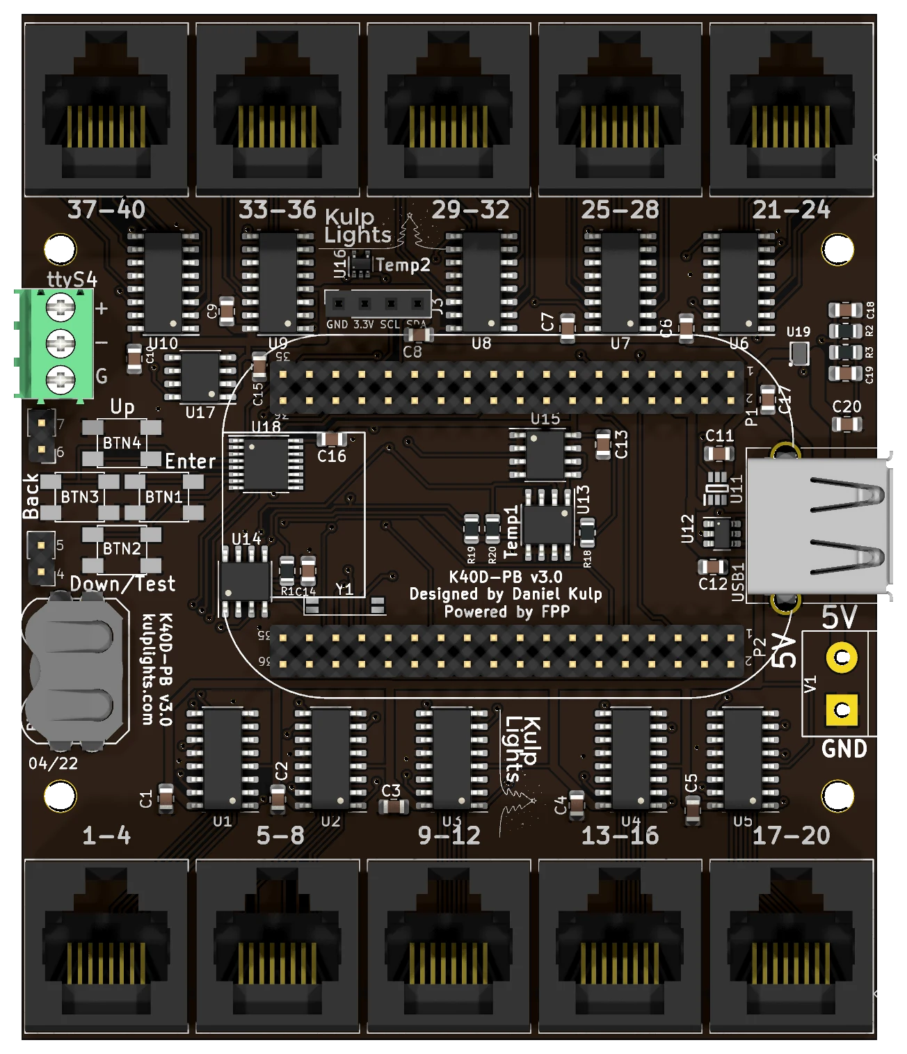
Power¶
The power terminal is on the right-hand edge, marked 5V (upper screw) and GND (lower screw). It powers only the PocketBeagle, the USB port and the board's logic, including the ten differential driver chips, which draw quite a bit. Use a regulated 5 V supply rated 4–5 A. The receivers power the pixels from their own supplies. FPP shows no input voltage reading on this board.
5 V only
Use a regulated 5 V supply. Don't connect 12 V or 24 V to the K40D-PB.
Differential ports¶
Each jack carries four strings, numbered as printed beside it:
| Top row, left to right | 37-40 |
33-36 |
29-32 |
25-28 |
21-24 |
| Bottom row, left to right | 1-4 |
5-8 |
9-12 |
13-16 |
17-20 |
The ports are send-only, with the standard four-strings-per-RJ45 pinout. Any standard differential receiver works, and smart receivers work in v1, v2 or V4 mode (FPP drives this board with its BBB48String output, which has no V5). Each string can drive up to 800 pixels at 40 fps. See Differential ports.
DMX¶
DMX is on the 3-pin, 3.5 mm pluggable terminal at the top of the left edge, marked ttyS4:
| Pin | Marking | Signal | DMX XLR pin |
|---|---|---|---|
| top | + |
Data + | 3 |
| middle | - |
Data − | 2 |
| bottom | G |
Ground | 1 |
Wire it to an XLR or RJ45 DMX connector as above. The output is transmit-only and can also drive
Renard, LOR or Pixelnet through a suitable adapter. FPP calls the port ttyS4. See
DMX / serial.
DMX on a PocketBeagle 2 with an older EEPROM
On a PocketBeagle 2, FPP finds this DMX port through a mapping in the cape EEPROM, added in
EEPROM 3.0.1 (February 2025). On a board programmed before then, a DMX output on ttyS4
goes to the wrong serial port and nothing comes out. Fix it by updating the cape EEPROM under
Help → About → Cape Info (see Updating), or set the DMX output's
port to ttyS5 instead. On a PocketBeagle 1, ttyS4 always works.
Other connectors¶
| Connector | Marking | Details |
|---|---|---|
| USB-A | — | 1 port, right-hand edge, for the network adapter. It sits over the PocketBeagle 2's SD card slot. USB |
| OLED | GND 3.3V SCL SDA |
top centre. Controls & display |
| Buttons | Up Back Enter Down/Test |
Down and Test share one button. Controls & display |
| GPIO | 4 5, 6 7 |
two 2-pin header positions on the left edge, unpopulated (solder in pins to use them). They are four spare lines on the button I/O expander, which FPP lists as Exp.4–Exp.7 on a PocketBeagle 2 (pca9674-4 to pca9674-7 on a PocketBeagle 1). Like the Exp header lines they are 3.3 V, pull up weakly and can only sink current: use them for switches to ground. |
| RTC battery | coin-cell holder, bottom left | Clock |
FPP setup¶
When FPP detects the K40D-PB it sets itself up automatically. It enables the K40D-PB
pixel-string layout (FPP's BBB48String output, with all 40 strings at 50 pixels each), the
temperature sensors, and a disabled DMX output on ttyS4. Set the pixel counts and start channels
from xLights or the FPP Pixel Strings page. See Configuring outputs.
For the first setup, plug in a USB Ethernet adapter and connect it to your network, or use a USB Wi-Fi adapter and FPP's Wi-Fi hotspot.
Dimensions & mounting¶
- 82.55 × 98.93 mm (3.25 × 3.89 in), 4 mounting holes, 3.0 mm, for M2.5 (or #4) screws and standoffs.
- Use standoffs at least 6 mm (¼ in) tall, so nothing on the underside touches the enclosure.
K16¶
16 fused pixel ports, 4 differential ports and DMX.
K16 with a PocketBeagle 2 fitted. Photos may show an earlier board revision.
This page describes revision v4.1.0 (printed on the board as K16 v4.1.0).
Specifications¶
| K16 | |
|---|---|
| Local pixel ports | 16 (P1–P16), 3-pin 3.5 mm pluggable, plugs included |
| Port protection | 5 A mini-blade fuse per port |
| Power switching | — |
| Current monitoring | — |
| Differential ports | 4 × RJ45 = 16 strings (17–32), send-only |
| Total strings | 32 |
| Power inputs | 4 terminals rated 30 A, 5–24 V DC, one bank of 4 ports each |
| DMX / serial | 1 (DMX), RS-485 transmit |
| Audio | none (use a USB sound card) |
| Ethernet | 1 × Gigabit (USB-attached) |
| USB-A | 1 (via the included extension cable) |
| Display & buttons | 128×64 OLED, Up / Down / Enter / Back / Test |
| Real-time clock | yes, CR1220 backup cell |
| Fan header | — |
| Expansion header | — |
| Size | 168.6 × 139.2 mm (6.64 × 5.48 in), 8 mounting holes, 3.0 mm |
| Requires | PocketBeagle 2 (not PocketBeagle 1), FPP 9.0 or later |
Board map¶
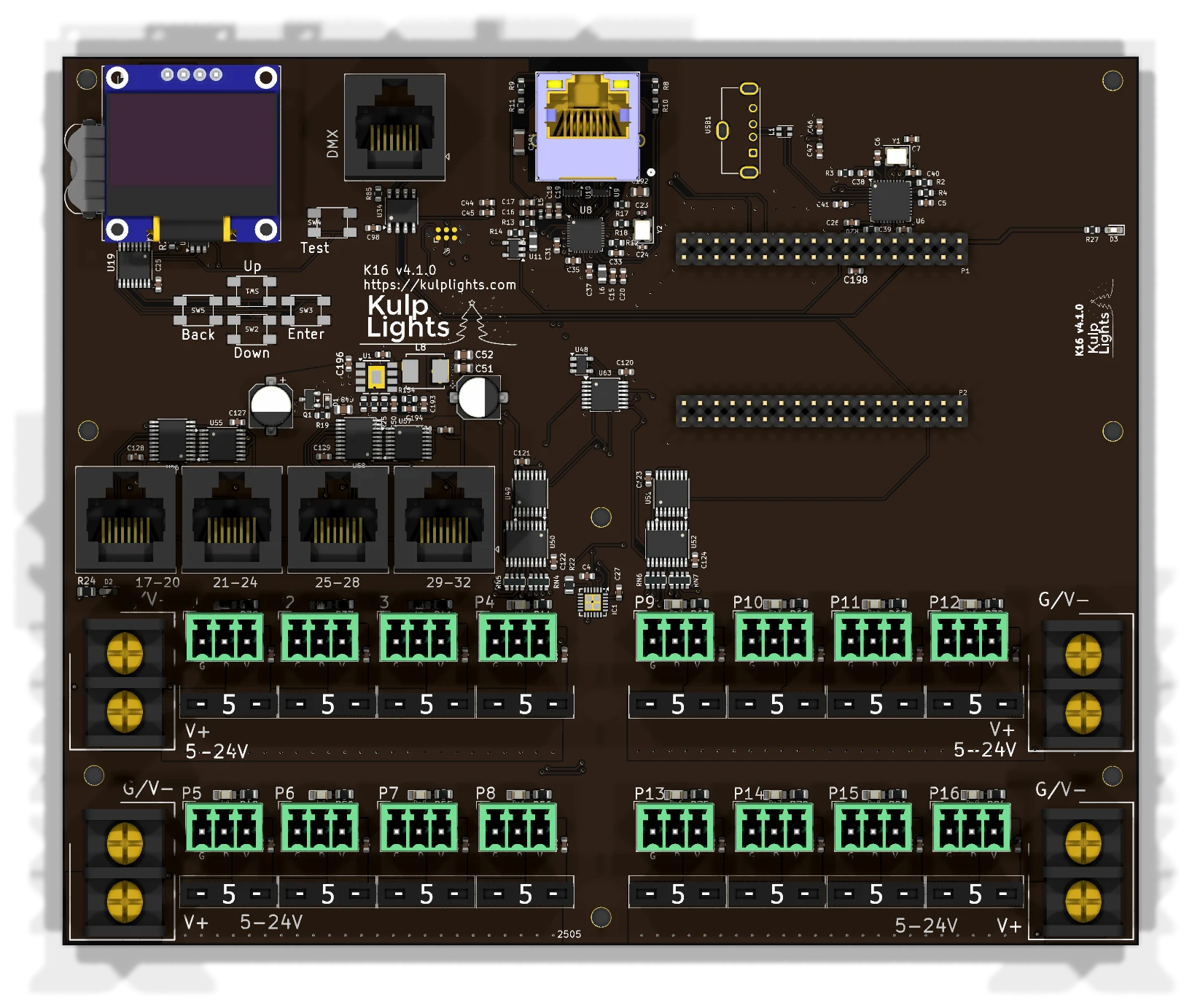
Power terminals¶
| Terminal | Position | Feeds | FPP reading | Also powers the controller? |
|---|---|---|---|---|
| V1 | left side, upper | P1–P4 | VIN1 | yes |
| V2 | left side, lower | P5–P8 | VIN2 | no |
| V3 | right side, upper | P9–P12 | VIN3 | no |
| V4 | right side, lower | P13–P16 | VIN4 | no |
The blue LED beside V1 lights when it has power. V1 must be powered for the controller to boot.
See Power for supply sizing, wire size and safety.
Pixel ports¶
The sixteen pixel ports are in two rows, eight on each side of the board's centre line:
| Left half | Right half | |
|---|---|---|
| Top row | P1 P2 P3 P4 | P9 P10 P11 P12 |
| Bottom row | P5 P6 P7 P8 | P13 P14 P15 P16 |
Each port is G D V (ground, data, +V), as printed beside it. See Pixel outputs.
Fuses¶
Every local port has a 5 A mini-blade fuse next to it. If a port's green LED is dark while the rest of its bank is lit, check that port's fuse first. Never fit a fuse larger than 5 A. See Power → Fuses.
Differential ports¶
17-20 · 21-24 · 25-28 · 29-32
Each jack carries four strings, numbered as printed above it. They are send-only. Any standard receiver works, but receivers cannot report back. See Differential ports.
Other connectors¶
| Connector | Marking | Details |
|---|---|---|
| Ethernet | (RJ45 with LEDs) | Network |
| DMX | DMX |
DMX / serial |
| USB-A | — | 1 port (use the included USB extension cable), USB |
| OLED | GND 3.3V SCL SDA |
Controls & display |
| RTC battery | coin-cell holder | Clock |
FPP setup¶
When FPP detects the K16 it sets itself up automatically. It enables the K16 pixel-string layout, the sensors (input voltages, temperature) and a disabled DMX output. Out of the box each local port is set to 50 WS2811 pixels at 50 % brightness. Set the real counts and start channels from xLights or the FPP Pixel Strings page. See Configuring outputs.
Dimensions & mounting¶
- 168.55 × 139.21 mm (6.64 × 5.48 in), 8 plated mounting holes, 3.0 mm, for M2.5 (or #4) screws and standoffs.
- The mounting holes are connected to ground.
- Use nylon or metal standoffs at least 6 mm (¼ in) tall, so nothing on the underside touches the enclosure.
- Mounting drawing: PDF. It is shared by the K16, K16-Pro and K16-Max, which have the same outline and holes.
- A 3D-printable mount is on Thingiverse.
K16-Pro¶
16 fused pixel ports with bank switching, 8 two-way differential ports, audio and 2 DMX.
K16-Pro with a PocketBeagle 2 fitted. Photos may show an earlier board revision.
This page describes revision v4.1.1 (printed on the board as K16-Pro v4.1.1). Differences in earlier revisions are listed under Board revisions.
Specifications¶
| K16-Pro | |
|---|---|
| Local pixel ports | 16 (P1–P16), 3-pin 3.5 mm pluggable, plugs included |
| Port protection | 5 A mini-blade fuse per port |
| Power switching | per bank of 4, FPP-controlled (v4.1 and later) |
| Current monitoring | from Falcon V5 receivers only |
| Differential ports | 8 × RJ45 = 32 strings (17–48), two-way (pair 1/2) |
| Total strings | 48 |
| Power inputs | 4 terminals rated 30 A, 5–24 V DC, one bank of 4 ports each |
| DMX / serial | 2 (DMX1, DMX2), RS-485 transmit |
| Audio | PCM5102A DAC, 3.5 mm line out, FM transmitter socket |
| Ethernet | 1 × Gigabit (USB-attached) |
| USB-A | 3 |
| Display & buttons | 128×64 OLED, Up / Down / Enter / Back / Test |
| Real-time clock | yes, CR1220 backup cell |
| Fan header | 5 V 4-pin PWM, temperature-controlled; speed monitoring on v4.1 and later |
| Expansion header | 2×6: I²C + 8 GPIO (Exp.1–Exp.8) |
| Size | 168.6 × 139.2 mm (6.64 × 5.48 in), 8 mounting holes, 3.0 mm |
| Requires | PocketBeagle 2 (not PocketBeagle 1), FPP 9.0 or later |
Board map¶
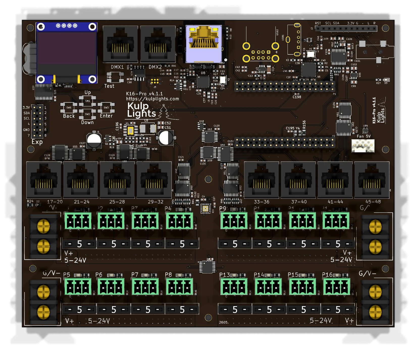
Power terminals¶
| Terminal | Position | Feeds | FPP reading | Also powers the controller? |
|---|---|---|---|---|
| V1 | left side, upper | P1–P4 | VIN1 | yes |
| V2 | left side, lower | P5–P8 | VIN2 | no |
| V3 | right side, upper | P9–P12 | VIN3 | no |
| V4 | right side, lower | P13–P16 | VIN4 | no |
The blue LED beside V1 lights when it has power. V1 must be powered for the controller to boot.
See Power for supply sizing, wire size and safety.
Pixel ports¶
The sixteen pixel ports are in two rows, eight on each side of the board's centre line:
| Left half | Right half | |
|---|---|---|
| Top row | P1 P2 P3 P4 | P9 P10 P11 P12 |
| Bottom row | P5 P6 P7 P8 | P13 P14 P15 P16 |
Each port is G D V (ground, data, +V), as printed beside it. See Pixel outputs.
Fuses¶
Every local port has a 5 A mini-blade fuse next to it. If a port's green LED is dark while the rest of its bank is lit, check that port's fuse first. Never fit a fuse larger than 5 A. See Power → Fuses.
Bank switching¶
Each bank of four ports has an electronic power switch that FPP controls, so FPP can turn pixel power off when nothing is playing. See Power → Bank switching.
Bank switching was added in v4.1. On a v4.0 board every bank is on whenever it has power. See Board revisions.
Differential ports¶
17-20 · 21-24 · 25-28 · 29-32 · 33-36 · 37-40 · 41-44 · 45-48
Each jack carries four strings, numbered as printed above it. They are two-way: Falcon V5 smart receivers report their eFuse status and current back over pair 1/2. Other receivers work as send-only. See Differential ports.
Other connectors¶
| Connector | Marking | Details |
|---|---|---|
| Ethernet | (RJ45 with LEDs) | Network |
| DMX | DMX1, DMX2 |
DMX / serial |
| USB-A | — | 3 ports, USB |
| OLED | GND 3.3V SCL SDA |
Controls & display |
| Audio out | 3.5 mm jack | Audio |
| FM transmitter | RST SCL SDA 3.3V G L R |
Audio |
| Fan | Fan 5V |
Fan |
| Expansion | Exp |
Expansion header |
| RTC battery | coin-cell holder | Clock |
FPP setup¶
When FPP detects the K16-Pro it sets itself up automatically. It enables the K16-Pro pixel-string layout, the sensors (input voltages, temperature), the audio output and a disabled DMX output. Out of the box each local port is set to 50 WS2811 pixels at 50 % brightness. Set the real counts and start channels from xLights or the FPP Pixel Strings page. See Configuring outputs.
Board revisions¶
The revision is printed on the board next to the model name. FPP also shows it as the Hardware Version under Help → About → Cape Info.
| Revision | Changes |
|---|---|
| v4.0 | Fused ports; banks are always on when powered. Fan speed control. |
| v4.1 | Adds bank switching (FPP turns each bank of 4 on and off) and fan speed monitoring. |
Dimensions & mounting¶
- 168.55 × 139.21 mm (6.64 × 5.48 in), 8 plated mounting holes, 3.0 mm, for M2.5 (or #4) screws and standoffs.
- The mounting holes are connected to ground.
- Use nylon or metal standoffs at least 6 mm (¼ in) tall, so nothing on the underside touches the enclosure.
- Mounting drawing: PDF. It is shared by the K16, K16-Pro and K16-Max, which have the same outline and holes.
- A 3D-printable mount is on Thingiverse.
K16-Max¶
16 eFused pixel ports with per-port current monitoring, 8 two-way differential ports, audio and 2 DMX.
K16-Max with a PocketBeagle 2 fitted. Photos may show an earlier board revision.
This page describes revision v4.1.0 (printed on the board as K16-Max v4.1.0). Differences in earlier revisions are listed under Board revisions.
Specifications¶
| K16-Max | |
|---|---|
| Local pixel ports | 16 (P1–P16), 3-pin 3.5 mm pluggable, plugs included |
| Port protection | eFuse per port, about 6 A, latching |
| Power switching | per port (FPP-controlled) |
| Current monitoring | every local port, plus Falcon V5 receivers |
| Differential ports | 8 × RJ45 = 32 strings (17–48), two-way (pair 1/2) |
| Total strings | 48 |
| Power inputs | 4 terminals rated 30 A, 5–24 V DC, one bank of 4 ports each |
| DMX / serial | 2 (DMX1, DMX2), RS-485 transmit |
| Audio | PCM5102A DAC, 3.5 mm line out, FM transmitter socket |
| Ethernet | 1 × Gigabit (USB-attached) |
| USB-A | 3 |
| Display & buttons | 128×64 OLED, Up / Down / Enter / Back / Test |
| Real-time clock | yes, CR1220 backup cell |
| Fan header | 5 V 4-pin PWM, temperature-controlled; speed monitoring on v4.1 and later |
| Expansion header | 2×6: I²C + 8 GPIO (Exp.1–Exp.8) |
| Size | 168.6 × 139.2 mm (6.64 × 5.48 in), 8 mounting holes, 3.0 mm |
| Requires | PocketBeagle 2 (not PocketBeagle 1), FPP 9.0 or later |
Board map¶
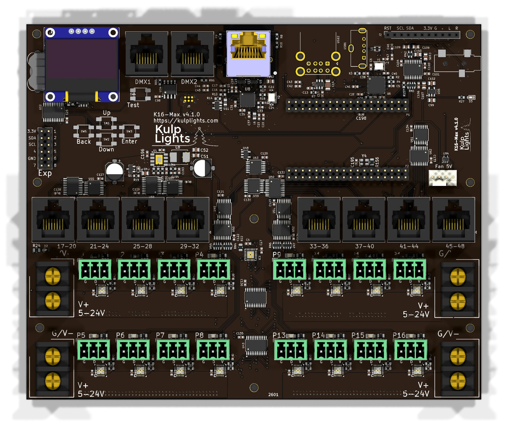
Power terminals¶
| Terminal | Position | Feeds | FPP reading | Also powers the controller? |
|---|---|---|---|---|
| V1 | left side, upper | P1–P4 | VIN1 | yes |
| V2 | left side, lower | P5–P8 | VIN2 | no |
| V3 | right side, upper | P9–P12 | VIN3 | no |
| V4 | right side, lower | P13–P16 | VIN4 | no |
The blue LED beside V1 lights when it has power. V1 must be powered for the controller to boot.
See Power for supply sizing, wire size and safety.
Pixel ports¶
The sixteen pixel ports are in two rows, eight on each side of the board's centre line:
| Left half | Right half | |
|---|---|---|
| Top row | P1 P2 P3 P4 | P9 P10 P11 P12 |
| Bottom row | P5 P6 P7 P8 | P13 P14 P15 P16 |
Each port is G D V (ground, data, +V), as printed beside it. See Pixel outputs.
eFuses and current monitoring¶
Every local port has its own eFuse (about 6 A), and FPP reads every port's current. FPP turns each port on and off as needed. A tripped port shows a red icon on Status/Control → Port Status; click it to reset the port once the fault is fixed. See Power → eFuses and Current monitoring.
Differential ports¶
17-20 · 21-24 · 25-28 · 29-32 · 33-36 · 37-40 · 41-44 · 45-48
Each jack carries four strings, numbered as printed above it. They are two-way: Falcon V5 smart receivers report their eFuse status and current back over pair 1/2. Other receivers work as send-only. See Differential ports.
Other connectors¶
| Connector | Marking | Details |
|---|---|---|
| Ethernet | (RJ45 with LEDs) | Network |
| DMX | DMX1, DMX2 |
DMX / serial |
| USB-A | — | 3 ports, USB |
| OLED | GND 3.3V SCL SDA |
Controls & display |
| Audio out | 3.5 mm jack | Audio |
| FM transmitter | RST SCL SDA 3.3V G L R |
Audio |
| Fan | Fan 5V |
Fan |
| Expansion | Exp |
Expansion header |
| RTC battery | coin-cell holder | Clock |
FPP setup¶
When FPP detects the K16-Max it sets itself up automatically. It enables the K16-Max pixel-string layout, the sensors (input voltages, port currents, temperature), the audio output and a disabled DMX output. Out of the box each local port is set to 50 WS2811 pixels at 50 % brightness. Set the real counts and start channels from xLights or the FPP Pixel Strings page. See Configuring outputs.
Board revisions¶
The revision is printed on the board next to the model name. FPP also shows it as the Hardware Version under Help → About → Cape Info.
| Revision | Changes |
|---|---|
| v4.0 | eFused ports with current monitoring. Fan speed control. |
| v4.1 | Adds fan speed monitoring. |
Dimensions & mounting¶
- 168.55 × 139.21 mm (6.64 × 5.48 in), 8 plated mounting holes, 3.0 mm, for M2.5 (or #4) screws and standoffs.
- The mounting holes are connected to ground.
- Use nylon or metal standoffs at least 6 mm (¼ in) tall, so nothing on the underside touches the enclosure.
- Mounting drawing: PDF. It is shared by the K16, K16-Pro and K16-Max, which have the same outline and holes.
- A 3D-printable mount is on Thingiverse.
K32¶
32 fused pixel ports, 4 differential ports and DMX.
K32, shown without a PocketBeagle 2. Photos may show an earlier board revision.
This page describes revision v4.1.0 (printed on the board as K32 v4.1.0).
Specifications¶
| K32 | |
|---|---|
| Local pixel ports | 32 (P1–P32), 3-pin 3.5 mm pluggable, plugs included |
| Port protection | 5 A mini-blade fuse per port |
| Power switching | — |
| Current monitoring | — |
| Differential ports | 4 × RJ45 = 16 strings (33–48), send-only |
| Total strings | 48 |
| Power inputs | 8 terminals rated 30 A, 5–24 V DC, one bank of 4 ports each |
| DMX / serial | 1 (DMX), RS-485 transmit |
| Audio | none (use a USB sound card) |
| Ethernet | 1 × Gigabit (USB-attached) |
| USB-A | 1 (via the included extension cable) |
| Display & buttons | 128×64 OLED, Up / Down / Enter / Back / Test |
| Real-time clock | yes, CR1220 backup cell |
| Fan header | — |
| Expansion header | — |
| Size | 168.6 × 202.8 mm (6.64 × 7.98 in), 11 mounting holes, 3.0 mm |
| Requires | PocketBeagle 2 (not PocketBeagle 1), FPP 9.0 or later |
Board map¶
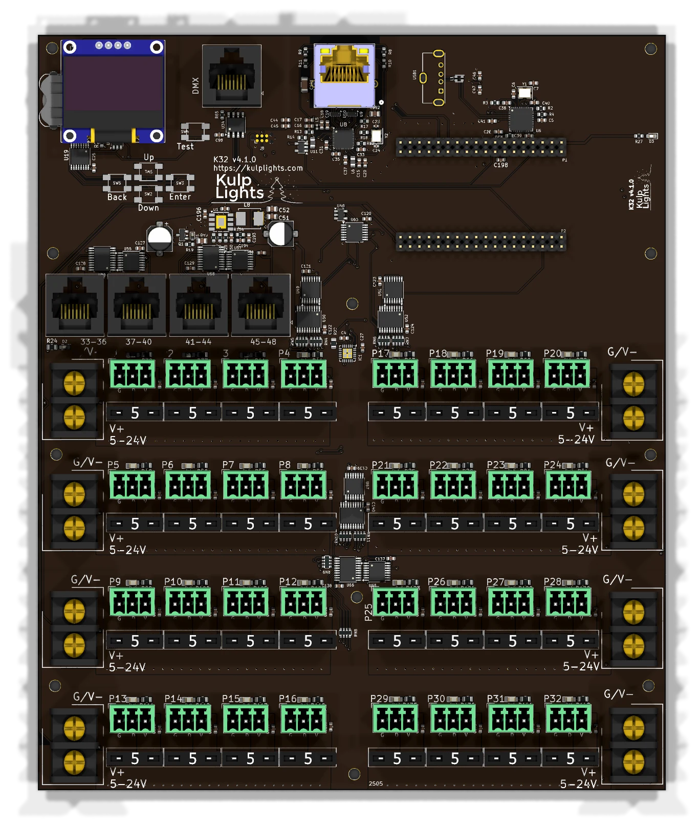
Power terminals¶
The four terminals down the left edge feed the left half of the board, and the four down the right edge feed the right half. FPP's VIN numbers don't follow reading order:
| Terminal | Position | Feeds | FPP reading | Also powers the controller? |
|---|---|---|---|---|
| V1 | left, row 1 (top) | P1–P4 | VIN1 | yes |
| V2 | left, row 2 | P5–P8 | VIN2 | no |
| V5 | left, row 3 | P9–P12 | VIN5 | no |
| V6 | left, row 4 | P13–P16 | VIN6 | no |
| V3 | right, row 1 (top) | P17–P20 | VIN3 | no |
| V4 | right, row 2 | P21–P24 | VIN4 | no |
| V7 | right, row 3 | P25–P28 | VIN7 | no |
| V8 | right, row 4 | P29–P32 | VIN8 | no |
The blue LED beside V1 lights when it has power. V1 must be powered for the controller to boot.
See Power for supply sizing, wire size and safety.
Pixel ports¶
The 32 pixel ports are in four rows of eight, four ports on each side:
| Left half | Right half | |
|---|---|---|
| Row 1 | P1–P4 | P17–P20 |
| Row 2 | P5–P8 | P21–P24 |
| Row 3 | P9–P12 | P25–P28 |
| Row 4 | P13–P16 | P29–P32 |
Each port is G D V (ground, data, +V), as printed beside it. See Pixel outputs.
Fuses¶
Every local port has a 5 A mini-blade fuse next to it. If a port's green LED is dark while the rest of its bank is lit, check that port's fuse first. Never fit a fuse larger than 5 A. See Power → Fuses.
Differential ports¶
33-36 · 37-40 · 41-44 · 45-48
Each jack carries four strings, numbered as printed above it. They are send-only. Any standard receiver works, but receivers cannot report back. See Differential ports.
Other connectors¶
| Connector | Marking | Details |
|---|---|---|
| Ethernet | (RJ45 with LEDs) | Network |
| DMX | DMX |
DMX / serial |
| USB-A | — | 1 port (use the included USB extension cable), USB |
| OLED | GND 3.3V SCL SDA |
Controls & display |
| RTC battery | coin-cell holder | Clock |
FPP setup¶
When FPP detects the K32 it sets itself up automatically. It enables the K32 pixel-string layout, the sensors (input voltages, temperature) and a disabled DMX output. Out of the box each local port is set to 50 WS2811 pixels at 50 % brightness. Set the real counts and start channels from xLights or the FPP Pixel Strings page. See Configuring outputs.
Dimensions & mounting¶
- 168.55 × 202.75 mm (6.64 × 7.98 in), 11 plated mounting holes, 3.0 mm, for M2.5 (or #4) screws and standoffs.
- The mounting holes are connected to ground.
- Use nylon or metal standoffs at least 6 mm (¼ in) tall, so nothing on the underside touches the enclosure.
- Mounting drawing: PDF · SVG. It is shared by the K32, K32-Pro and K32-Max, which have the same outline and holes.
- A 3D-printable mount is on Thingiverse.

K32-Pro¶
32 fused pixel ports, 8 two-way differential ports, audio and 2 DMX.
K32-Pro with a PocketBeagle 2 fitted. Photos may show an earlier board revision.
This page describes revision v4.1.0 (printed on the board as K32-Pro v4.1.0). Differences in earlier revisions are listed under Board revisions.
Specifications¶
| K32-Pro | |
|---|---|
| Local pixel ports | 32 (P1–P32), 3-pin 3.5 mm pluggable, plugs included |
| Port protection | 5 A mini-blade fuse per port |
| Power switching | per bank of 4, FPP-controlled (v4.1 and later) |
| Current monitoring | from Falcon V5 receivers only |
| Differential ports | 8 × RJ45 = 32 strings (33–64), two-way (pair 1/2) |
| Total strings | 64 |
| Power inputs | 8 terminals rated 30 A, 5–24 V DC, one bank of 4 ports each |
| DMX / serial | 2 (DMX1, DMX2), RS-485 transmit |
| Audio | PCM5102A DAC, 3.5 mm line out, FM transmitter socket |
| Ethernet | 1 × Gigabit (USB-attached) |
| USB-A | 3 |
| Display & buttons | 128×64 OLED, Up / Down / Enter / Back / Test |
| Real-time clock | yes, CR1220 backup cell |
| Fan header | 5 V 4-pin PWM, temperature-controlled; speed monitoring on v4.1 and later |
| Expansion header | 2×6: I²C + 8 GPIO (Exp.1–Exp.8) |
| Size | 168.6 × 202.8 mm (6.64 × 7.98 in), 11 mounting holes, 3.0 mm |
| Requires | PocketBeagle 2 (not PocketBeagle 1), FPP 9.0 or later |
Board map¶
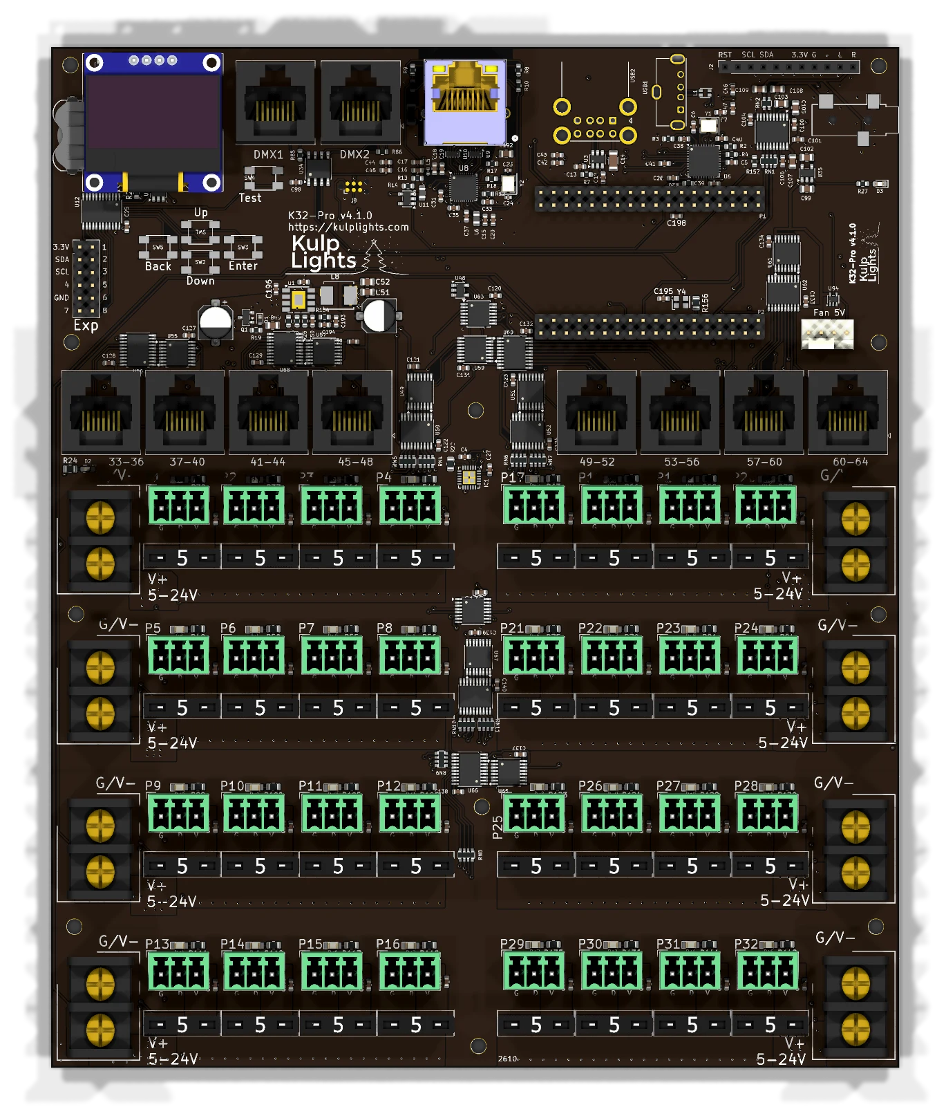
Power terminals¶
The four terminals down the left edge feed the left half of the board, and the four down the right edge feed the right half. FPP's VIN numbers don't follow reading order:
| Terminal | Position | Feeds | FPP reading | Also powers the controller? |
|---|---|---|---|---|
| V1 | left, row 1 (top) | P1–P4 | VIN1 | yes |
| V2 | left, row 2 | P5–P8 | VIN2 | no |
| V5 | left, row 3 | P9–P12 | VIN5 | no |
| V6 | left, row 4 | P13–P16 | VIN6 | no |
| V3 | right, row 1 (top) | P17–P20 | VIN3 | no |
| V4 | right, row 2 | P21–P24 | VIN4 | no |
| V7 | right, row 3 | P25–P28 | VIN7 | no |
| V8 | right, row 4 | P29–P32 | VIN8 | no |
The blue LED beside V1 lights when it has power. V1 must be powered for the controller to boot.
See Power for supply sizing, wire size and safety.
Pixel ports¶
The 32 pixel ports are in four rows of eight, four ports on each side:
| Left half | Right half | |
|---|---|---|
| Row 1 | P1–P4 | P17–P20 |
| Row 2 | P5–P8 | P21–P24 |
| Row 3 | P9–P12 | P25–P28 |
| Row 4 | P13–P16 | P29–P32 |
Each port is G D V (ground, data, +V), as printed beside it. See Pixel outputs.
Fuses¶
Every local port has a 5 A mini-blade fuse next to it. If a port's green LED is dark while the rest of its bank is lit, check that port's fuse first. Never fit a fuse larger than 5 A. See Power → Fuses.
Bank switching¶
Each bank of four ports has an electronic power switch that FPP controls, so FPP can turn pixel power off when nothing is playing. See Power → Bank switching.
Bank switching was added in v4.1. On a v4.0 board every bank is on whenever it has power. See Board revisions.
Differential ports¶
33-36 · 37-40 · 41-44 · 45-48 · 49-52 · 53-56 · 57-60 · 61-64
Each jack carries four strings, numbered as printed above it. They are two-way: Falcon V5 smart receivers report their eFuse status and current back over pair 1/2. Other receivers work as send-only. See Differential ports.
Note
On earlier boards the last differential jack is printed 60-64. It carries strings 61–64.
Other connectors¶
| Connector | Marking | Details |
|---|---|---|
| Ethernet | (RJ45 with LEDs) | Network |
| DMX | DMX1, DMX2 |
DMX / serial |
| USB-A | — | 3 ports, USB |
| OLED | GND 3.3V SCL SDA |
Controls & display |
| Audio out | 3.5 mm jack | Audio |
| FM transmitter | RST SCL SDA 3.3V G L R |
Audio |
| Fan | Fan 5V |
Fan |
| Expansion | Exp |
Expansion header |
| RTC battery | coin-cell holder | Clock |
FPP setup¶
When FPP detects the K32-Pro it sets itself up automatically. It enables the K32-Pro pixel-string layout, the sensors (input voltages, temperature), the audio output and a disabled DMX output. Out of the box each local port is set to 50 WS2811 pixels at 50 % brightness. Set the real counts and start channels from xLights or the FPP Pixel Strings page. See Configuring outputs.
Board revisions¶
The revision is printed on the board next to the model name. FPP also shows it as the Hardware Version under Help → About → Cape Info.
| Revision | Changes |
|---|---|
| v4.0 | Fused ports; banks are always on when powered. Fan speed control. |
| v4.1 | Adds bank switching (FPP turns each bank of 4 on and off) and fan speed monitoring. |
Dimensions & mounting¶
- 168.55 × 202.75 mm (6.64 × 7.98 in), 11 plated mounting holes, 3.0 mm, for M2.5 (or #4) screws and standoffs.
- The mounting holes are connected to ground.
- Use nylon or metal standoffs at least 6 mm (¼ in) tall, so nothing on the underside touches the enclosure.
- Mounting drawing: PDF · SVG. It is shared by the K32, K32-Pro and K32-Max, which have the same outline and holes.
- A 3D-printable mount is on Thingiverse.
K32-Max¶
32 eFused pixel ports with per-port current monitoring, 8 two-way differential ports, audio and 2 DMX.
K32-Max with a PocketBeagle 2 fitted. Photos may show an earlier board revision.
This page describes revision v4.2.0 (printed on the board as K32-Max v4.2.0). Differences in earlier revisions are listed under Board revisions.
Specifications¶
| K32-Max | |
|---|---|
| Local pixel ports | 32 (P1–P32), 3-pin 3.5 mm pluggable, plugs included |
| Port protection | eFuse per port, about 6 A, latching |
| Power switching | per port (FPP-controlled) |
| Current monitoring | every local port, plus Falcon V5 receivers |
| Differential ports | 8 × RJ45 = 32 strings (33–64), two-way (pair 1/2) |
| Total strings | 64 |
| Power inputs | 8 terminals rated 30 A, 5–24 V DC, one bank of 4 ports each |
| DMX / serial | 2 (DMX1, DMX2), RS-485 transmit |
| Audio | PCM5102A DAC, 3.5 mm line out, FM transmitter socket |
| Ethernet | 1 × Gigabit (USB-attached) |
| USB-A | 3 |
| Display & buttons | 128×64 OLED, Up / Down / Enter / Back / Test |
| Real-time clock | yes, CR1220 backup cell |
| Fan header | 5 V 4-pin PWM, temperature-controlled; speed monitoring on v4.1 and later |
| Expansion header | 2×6: I²C + 8 GPIO (Exp.1–Exp.8) |
| Size | 168.6 × 202.8 mm (6.64 × 7.98 in), 11 mounting holes, 3.0 mm |
| Requires | PocketBeagle 2 (not PocketBeagle 1), FPP 9.0 or later |
Board map¶
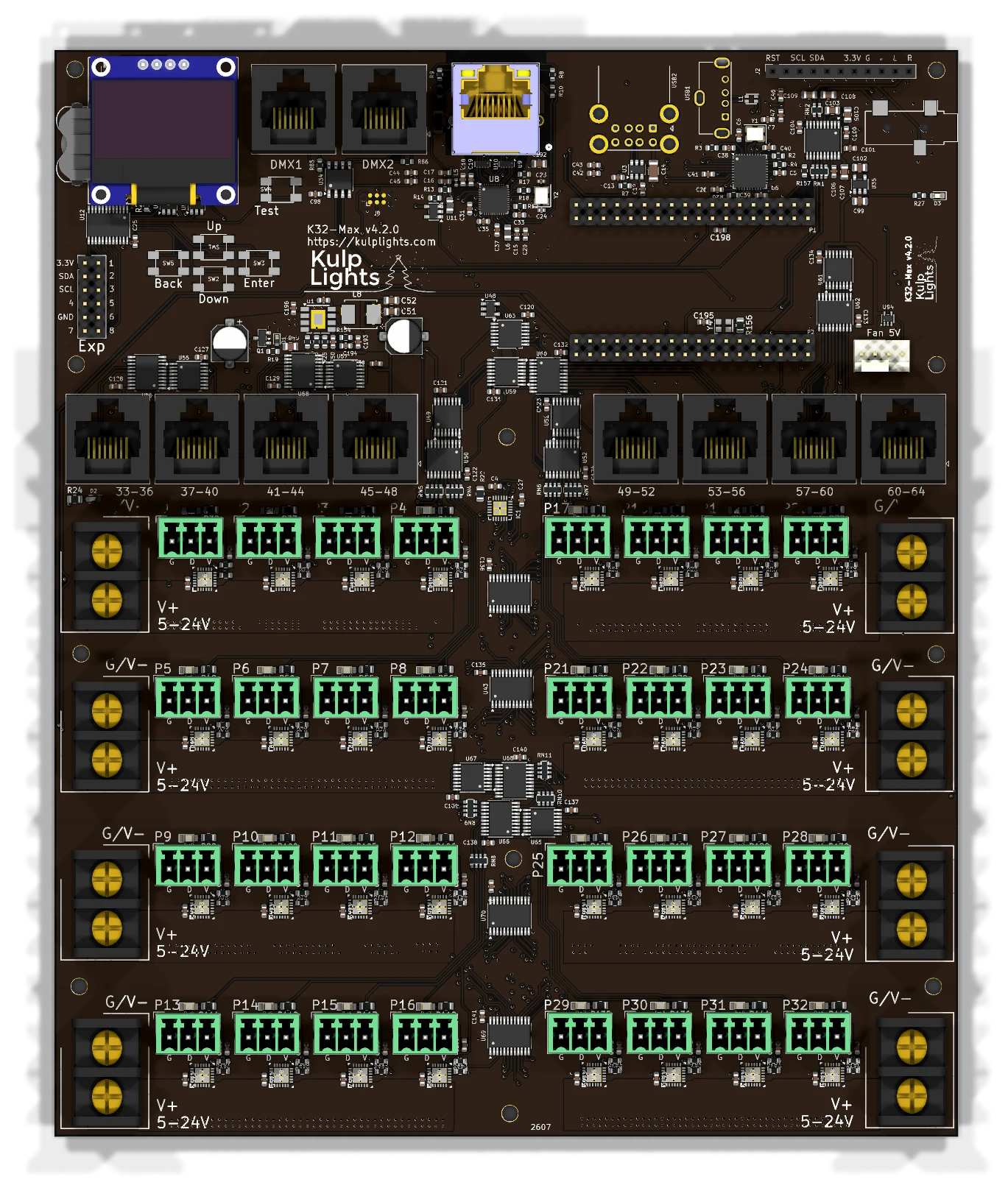
Power terminals¶
The four terminals down the left edge feed the left half of the board, and the four down the right edge feed the right half. FPP's VIN numbers don't follow reading order:
| Terminal | Position | Feeds | FPP reading | Also powers the controller? |
|---|---|---|---|---|
| V1 | left, row 1 (top) | P1–P4 | VIN1 | yes |
| V2 | left, row 2 | P5–P8 | VIN2 | no |
| V5 | left, row 3 | P9–P12 | VIN5 | no |
| V6 | left, row 4 | P13–P16 | VIN6 | no |
| V3 | right, row 1 (top) | P17–P20 | VIN3 | no |
| V4 | right, row 2 | P21–P24 | VIN4 | no |
| V7 | right, row 3 | P25–P28 | VIN7 | no |
| V8 | right, row 4 | P29–P32 | VIN8 | no |
The blue LED beside V1 lights when it has power. V1 must be powered for the controller to boot.
See Power for supply sizing, wire size and safety.
Pixel ports¶
The 32 pixel ports are in four rows of eight, four ports on each side:
| Left half | Right half | |
|---|---|---|
| Row 1 | P1–P4 | P17–P20 |
| Row 2 | P5–P8 | P21–P24 |
| Row 3 | P9–P12 | P25–P28 |
| Row 4 | P13–P16 | P29–P32 |
Each port is G D V (ground, data, +V), as printed beside it. See Pixel outputs.
eFuses and current monitoring¶
Every local port has its own eFuse (about 6 A), and FPP reads every port's current. FPP turns each port on and off as needed. A tripped port shows a red icon on Status/Control → Port Status; click it to reset the port once the fault is fixed. See Power → eFuses and Current monitoring.
Differential ports¶
33-36 · 37-40 · 41-44 · 45-48 · 49-52 · 53-56 · 57-60 · 61-64
Each jack carries four strings, numbered as printed above it. They are two-way: Falcon V5 smart receivers report their eFuse status and current back over pair 1/2. Other receivers work as send-only. See Differential ports.
Note
On earlier boards the last differential jack is printed 60-64. It carries strings 61–64.
Other connectors¶
| Connector | Marking | Details |
|---|---|---|
| Ethernet | (RJ45 with LEDs) | Network |
| DMX | DMX1, DMX2 |
DMX / serial |
| USB-A | — | 3 ports, USB |
| OLED | GND 3.3V SCL SDA |
Controls & display |
| Audio out | 3.5 mm jack | Audio |
| FM transmitter | RST SCL SDA 3.3V G L R |
Audio |
| Fan | Fan 5V |
Fan |
| Expansion | Exp |
Expansion header |
| RTC battery | coin-cell holder | Clock |
FPP setup¶
When FPP detects the K32-Max it sets itself up automatically. It enables the K32-Max pixel-string layout, the sensors (input voltages, port currents, temperature), the audio output and a disabled DMX output. Out of the box each local port is set to 50 WS2811 pixels at 50 % brightness. Set the real counts and start channels from xLights or the FPP Pixel Strings page. See Configuring outputs.
Board revisions¶
The revision is printed on the board next to the model name. FPP also shows it as the Hardware Version under Help → About → Cape Info.
| Revision | Changes |
|---|---|
| v4.0 | eFused ports with current monitoring. Fan speed control. |
| v4.1 | Adds fan speed monitoring. |
| v4.2 | Adds a dedicated audio clock oscillator. |
Dimensions & mounting¶
- 168.55 × 202.75 mm (6.64 × 7.98 in), 11 plated mounting holes, 3.0 mm, for M2.5 (or #4) screws and standoffs.
- The mounting holes are connected to ground.
- Use nylon or metal standoffs at least 6 mm (¼ in) tall, so nothing on the underside touches the enclosure.
- Mounting drawing: PDF · SVG. It is shared by the K32, K32-Pro and K32-Max, which have the same outline and holes.
- A 3D-printable mount is on Thingiverse.
PocketScroller v2¶
Six HUB75 outputs for LED panel matrices, on a small board that works with either PocketBeagle.
PocketScroller v2 (v2.2) shown with an original PocketBeagle (PocketBeagle 1) fitted.
This page covers the PocketScroller v2, printed on the board as PocketScroller+ v2.x (the current
revision is v2.3). Like the K4-PB and K40D-PB, it works with both the PocketBeagle 2 and the original
PocketBeagle 1.
How the PocketScroller v2 differs from the other boards
- No Ethernet on the board. Plug a USB Ethernet adapter or an FPP-supported USB Wi-Fi adapter into its USB-A port. You need one of them to set it up.
- The USB-A port covers the PocketBeagle 2's SD card slot. To change the SD card you have to unplug the PocketBeagle 2. Either use a PocketBeagle 2 Industrial, which runs FPP from its built-in eMMC (recommended), or fit the PB2 microSD extender, which clears the USB port.
- The OLED shares pins with output 6. If you use all six outputs, the OLED shows information while the board boots and then turns off once FPP starts. Leave output 6 free if you can.
- No real-time clock. The board gets the time from the network (NTP).
- 5 V only, like the other PocketScrollers.
PocketBeagle 1: never connect its USB port to a computer
With an original PocketBeagle 1 fitted, don't power or set up the PocketScroller v2 through the PocketBeagle's own USB port (USB tethering). It can permanently damage the board. With a PocketBeagle 2, USB tethering is safe.
Specifications¶
| PocketScroller v2 | |
|---|---|
| Panel outputs | 6 × HUB75 (2×8 shrouded header), no E line |
| Panel types | 1/4, 1/8 and 1/16 scan (for example P10 1/4 or 1/8, P5 1/8 or 1/16). Not 1/32 scan. |
| Capacity | see Capacity & refresh rate |
| Signal level | 3.3 V data from the PocketBeagle; control lines buffered to 5 V |
| Power input | 5 V DC only, 2-pin 3.5 mm screw terminal |
| Panel power | not supplied. Panels need their own 5 V supply. |
| Ethernet | none. Use a USB Ethernet or Wi-Fi adapter. |
| USB-A | 1 |
| Display & buttons | 128×64 OLED (off when output 6 is in use), Down-Test / Enter |
| Real-time clock | none |
| Temperature sensor | yes |
| Expansion header | none |
| Size | 60.96 × 72.52 mm (2.40 × 2.86 in), 5 mounting holes, 3.0 mm |
| Requires | PocketBeagle 2 (FPP 9.5 or later, FPP 10 or later strongly recommended) or PocketBeagle 1 |
Board map¶
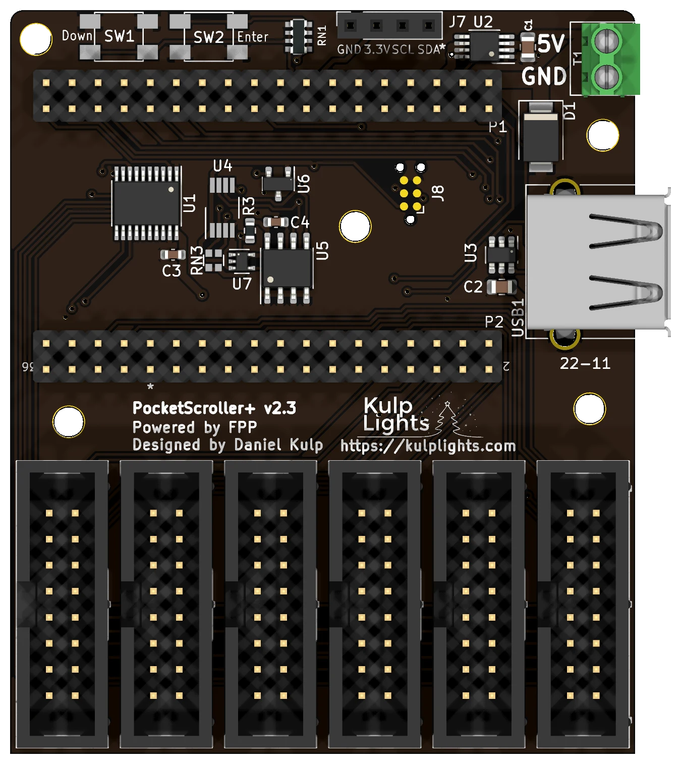
Power¶
5 V only
The PocketScroller v2 has no voltage regulator. Connect a regulated 5 V supply to the terminal at the top right, marked 5V (upper screw) and GND (lower screw). A 12 V or 24 V supply will damage the board and the PocketBeagle.
- The terminal powers the PocketBeagle, the output buffer and the USB port. The board itself draws very little.
- The panels are not powered through the PocketScroller. Run each panel's power from your 5 V panel supply. You can feed the PocketScroller from the same supply.
- There are no power LEDs. When the board is running, the OLED shows status (as long as output 6 is free).
Panel outputs¶
The six HUB75 outputs are along the bottom edge, Output 1 on the left to Output 6 on the right. They aren't numbered on the board. Connect each chain of panels with a 16-pin ribbon cable to the panel's input connector.
Output 6 and the OLED
The OLED's I²C lines share pins with output 6. While output 6 is unused, FPP keeps the OLED running. When you configure panels on output 6, FPP takes the pins for the panels and the OLED goes dark after boot. If you need fewer than six outputs, use outputs 1–5.
Set the panels up in FPP under Input/Output Setup → Channel Outputs → LED Panels. See LED panel matrices in the FPP manual.
Buttons and OLED¶
The two buttons at the top left are marked Down (left) and Enter (right). The left button is also Test: on the status page it starts and cycles the test patterns; in menus it moves down. See Controls & display.
The OLED plugs into the 4-pin socket marked GND 3.3V SCL SDA.
Other connectors¶
| Connector | Details |
|---|---|
| USB-A | 1 port, for the network adapter. It sits over the PocketBeagle 2's SD card slot; the PB2 microSD extender clears it. USB |
| PocketBeagle | sockets P1 (upper) and P2 (lower). See PocketBeagle 2. |
Capacity & refresh rate¶
How many panels you can run depends on how long each chain is and on the colour depth. The tables give the full-frame refresh rate in Hz for 64×32, 1/16-scan panels at FPP's default brightness (10), with all six outputs in use. Bold values are 60 Hz or more. Italic values are under 60 Hz, where flicker starts to show on camera and to some viewers.
| Panels per output | Total panels | 12-bit | 10-bit | 8-bit |
|---|---|---|---|---|
| 1 | 6 | 112 | 134 | 202 |
| 2 | 12 | 72 | 86 | 118 |
| 3 | 18 | 51 | 62 | 80 |
| 4 | 24 | 40 | 48 | 60 |
| 5 | 30 | 32 | 39 | 48 |
| 6 | 36 | 27 | 32 | 40 |
| 8 | 48 | 20 | 24 | 30 |
| 10 | 60 | 16 | 19 | 24 |
| 12 | 72 | 14 | 16 | 20 |
| 16 | 96 | 10 | 12 | 15 |
Rule of thumb at 60 Hz: up to 2 panels per output at 12-bit colour (12 panels), or 4 per output at 8-bit (24 panels).
| Panels per output | Total panels | 12-bit | 10-bit | 8-bit |
|---|---|---|---|---|
| 1 | 6 | 114 | 135 | 220 |
| 2 | 12 | 82 | 98 | 145 |
| 3 | 18 | 63 | 76 | 106 |
| 4 | 24 | 50 | 61 | 79 |
| 5 | 30 | 42 | 50 | 64 |
| 6 | 36 | 36 | 43 | 53 |
| 8 | 48 | 27 | 32 | 40 |
| 10 | 60 | 22 | 26 | 32 |
| 12 | 72 | 18 | 22 | 27 |
| 16 | 96 | 14 | 16 | 20 |
Rule of thumb at 60 Hz: up to 3 panels per output at 12-bit colour (18 panels), or 5 per output at 8-bit (30 panels).
- These are measured, worst-case figures, with random pixel data on every panel. Flat colours and large solid areas refresh faster, by up to about 40 %.
- The PocketBeagle 1 is faster on longer chains. Past 2 panels per output the PocketScroller v2 runs about 25 % slower on a PocketBeagle 2. If you need the most panels at a high refresh rate, the PocketScroller v3 or PocketScroller-16 is a better fit on a PocketBeagle 2.
- Number of outputs: on a PocketBeagle 2, one output refreshes at the same rate as all six, so spread the panels evenly. On a PocketBeagle 1, a single output is 25–35 % faster than six, and from three outputs up the rate doesn't change.
- 1/8-scan outdoor panels refresh at the same rate or a little faster than these 1/16-scan figures. The gain is largest on short chains and fades to nothing by about 8 panels per output.
- Lowering colour depth is the easiest way to win back refresh. Unlike the v3 and -16, lowering the brightness setting makes the PocketScroller v2 slightly slower, because it adds off-time.
FPP setup¶
When FPP detects the PocketScroller v2 it offers the PocketScroller wiring for LED panels. Add an LED Panels output and your panel layout under Input/Output Setup → Channel Outputs → LED Panels.
For the first setup, plug a USB Ethernet adapter into the USB-A port and connect it to your network, or use a USB Wi-Fi adapter and FPP's Wi-Fi hotspot. Because the board has no clock, set up NTP under Settings → Time so schedules run at the right time.
Dimensions & mounting¶
- 60.96 × 72.52 mm (2.40 × 2.86 in), 5 plated mounting holes, 3.0 mm, for M2.5 (or #4) screws and standoffs.
- Use nylon or metal standoffs at least 6 mm (¼ in) tall, so nothing on the underside touches the enclosure.
PocketScroller v3¶
Eight HUB75 outputs for driving LED panel matrices from a PocketBeagle 2.
PocketScroller v3 with a PocketBeagle 2 fitted.
This page covers board revision v3.0.0. The board is sold as the PocketScroller v3, but printed
on it as PocketScroller+ v3.0.0.
FPP calls it PocketScroller.
Specifications¶
| PocketScroller v3 | |
|---|---|
| Panel outputs | 8 × HUB75 (2×8 shrouded header), with E line for 1/32-scan panels |
| Capacity | about 80 64×32 panels at 12-bit colour and 60 Hz (10 per output); see Capacity |
| Signal level | 5 V |
| Power input | 5 V DC only, 2-pin 5.08 mm screw terminal |
| Input protection | 3 A resettable fuse, over-voltage clamp, reverse-polarity protection |
| Panel power | not supplied. Panels need their own 5 V supply. |
| Ethernet | 1 × Gigabit (USB-attached) |
| USB-A | 3 |
| Display & buttons | 128×64 OLED, Up / Down / Enter / Back / Test |
| Real-time clock | yes, CR1220 backup cell |
| Expansion header | 2×6: I²C + 8 GPIO (Exp.1–Exp.8) |
| Audio, DMX, pixel ports | none |
| Size | 121.95 × 100.70 mm (4.80 × 3.96 in), 6 mounting holes, 3.0 mm |
| Requires | PocketBeagle 2 (not PocketBeagle 1), FPP 9.0 or later |
Board map¶
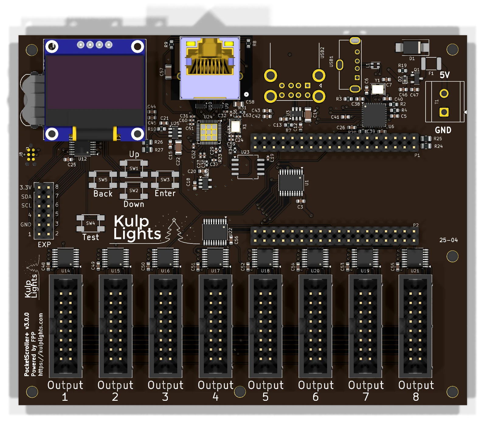
Power¶
5 V only
The PocketScroller v3 has no voltage regulator. Connect a regulated 5 V supply to the terminal marked 5V / GND (top-right corner). A 12 V or 24 V supply makes the protection clamp conduct and trip the resettable fuse, and can damage the board.
- The terminal powers the PocketBeagle 2, the panel drivers, Ethernet and the USB ports. The board draws very little, but use a 5 V supply rated 5 A or more: it handles ripple and spikes better.
- The panels are not powered through the PocketScroller. Run each panel's power from your 5 V panel supply. You can feed the PocketScroller from the same supply.
- There are no power LEDs. When the board is running, the OLED shows status.
- FPP shows the input voltage as VIN.
Panel outputs¶
The eight outputs run along the bottom edge, marked Output 1 to Output 8 from left to right. Each is a standard HUB75 connector:
| Pin | Signal | Pin | Signal |
|---|---|---|---|
| 1 | R1 | 2 | G1 |
| 3 | B1 | 4 | GND |
| 5 | R2 | 6 | G2 |
| 7 | B2 | 8 | E |
| 9 | A | 10 | B |
| 11 | C | 12 | D |
| 13 | CLK | 14 | LAT |
| 15 | OE | 16 | GND |
- Use the ribbon cables that come with your panels. The red stripe goes to pin 1 (marked on the header's shroud).
- Chain panels from each output's input connector to the next panel's input, following the arrows on the panels.
- Spread the panels evenly across all eight outputs. The refresh rate depends on the longest chain (see Capacity & refresh rate).
Other connectors¶
| Connector | Marking | Details |
|---|---|---|
| Ethernet | (RJ45 with LEDs) | Network |
| USB-A | — | 3 ports, USB |
| OLED | GND 3.3V SCL SDA |
Controls & display |
| Expansion | EXP |
Expansion header (PocketScroller pinout) |
| RTC battery | coin-cell holder, top-left | Clock |
Capacity & refresh rate¶
How many panels you can run depends on how long each chain is and on the colour depth. The table gives the full-frame refresh rate in Hz for 64×32 panels at FPP's default brightness (10). Bold values are 60 Hz or more. Italic values are under 60 Hz, where flicker starts to show on camera and to some viewers.
| Panels per output | Total panels | 12-bit | 10-bit | 8-bit | PWM panels (fps) |
|---|---|---|---|---|---|
| 1 | 8 | 192 | 200 | 210 | 545 |
| 2 | 16 | 166 | 179 | 194 | 272 |
| 3 | 24 | 143 | 157 | 174 | 182 |
| 4 | 32 | 128 | 143 | 162 | 136 |
| 5 | 40 | 110 | 124 | 143 | 109 |
| 6 | 48 | 96 | 108 | 126 | 91 |
| 8 | 64 | 75 | 86 | 100 | 68 |
| 10 | 80 | 60 | 69 | 81 | 54 |
| 12 | 96 | 54 | 62 | 73 | 45 |
| 16 | 128 | 45 | 53 | 64 | 34 |
- Rule of thumb at 60 Hz: up to 10 panels per output at 12-bit colour (80 panels), or 16 per output at 8-bit (128 panels).
- Refresh depends only on the longest chain. Every output is clocked whether or not a panel is attached, so using fewer outputs doesn't make it faster. Spread the panels evenly across all 8 outputs.
- 1/8-scan outdoor panels refresh within a few percent of these 1/16-scan figures. Panels with shift-register row drivers ("ABC-shift" addressing, found on some outdoor 1/8 panels) are 7–16 % slower.
- Lowering colour depth is the easiest way to win back refresh on long chains. Lowering the brightness setting raises refresh slightly (about 9 % at brightness 8).
- The brightest bit plane is split into up to four pulses per frame, so the flicker a viewer actually sees runs 2–4× faster than the full-frame figure.
Estimated figures
These numbers come from FPP's refresh estimator for the 8-output firmware. On the PocketScroller-16 the same estimator matched hardware measurements to within 0.5 %, but the 8-output timing hasn't been measured on a board yet.
PWM panels¶
Panels with PWM driver chips (FM6363C, FM6353, FM6373) run their own 16-bit greyscale, so they don't flicker as chains get longer. Chain length limits only how many new frames per second reach the panels: the last column of the table. Bold values there meet a 40 fps sequence, which works out to up to 12 panels per output (96 panels). Select the panel's driver chip under Panel Type in FPP's LED Panels settings.
FPP setup¶
When FPP detects the PocketScroller it sets up an LED Panels output (Input/Output Setup → Channel Outputs → LED Panels) with the PocketScroller v3 wiring. The starting layout is a 2×2 block of 64×32 panels at low brightness. Change it to match your panels:
- Set the panel size and scan (e.g. 64×32 1/16, 64×64 1/32).
- Set the layout: how many panels wide and high.
- In the grid, assign each panel to an output and a position in the chain, and set its orientation.
- Set colour depth and brightness, then save. FPP restarts the output.
See LED panel matrices in the FPP manual for every field.
Dimensions & mounting¶

PocketScroller-16¶
Sixteen HUB75 outputs for large LED panel matrices from a PocketBeagle 2. It's the bigger sibling of the PocketScroller v3, with the same power input, controls and expansion header, and twice the outputs.
PocketScroller-16 with a PocketBeagle 2 fitted.
This page covers board revision v3.0.0 (printed on the board as PocketScroller-16 v3.0.0).
FPP calls it PocketScroller-16.
Specifications¶
| PocketScroller-16 | |
|---|---|
| Panel outputs | 16 × HUB75 (2×8 shrouded header), with E line for 1/32-scan panels |
| Capacity | 96 64×32 panels at 12-bit colour and 60 Hz (6 per output); see Capacity |
| Signal level | 5 V |
| Power input | 5 V DC only, 2-pin 5.08 mm screw terminal |
| Input protection | 3 A resettable fuse, over-voltage clamp, reverse-polarity protection |
| Panel power | not supplied. Panels need their own 5 V supply. |
| Ethernet | 1 × Gigabit (USB-attached) |
| USB-A | 3 |
| Display & buttons | 128×64 OLED, Up / Down / Enter / Back / Test |
| Real-time clock | yes, CR1220 backup cell |
| Expansion header | 2×6: I²C + 8 GPIO (Exp.1–Exp.8) |
| Audio, DMX, pixel ports | none |
| Size | 121.95 × 144.21 mm (4.80 × 5.68 in), 7 mounting holes, 3.0 mm |
| Requires | PocketBeagle 2 (not PocketBeagle 1), FPP 10.0 or later |
Board map¶
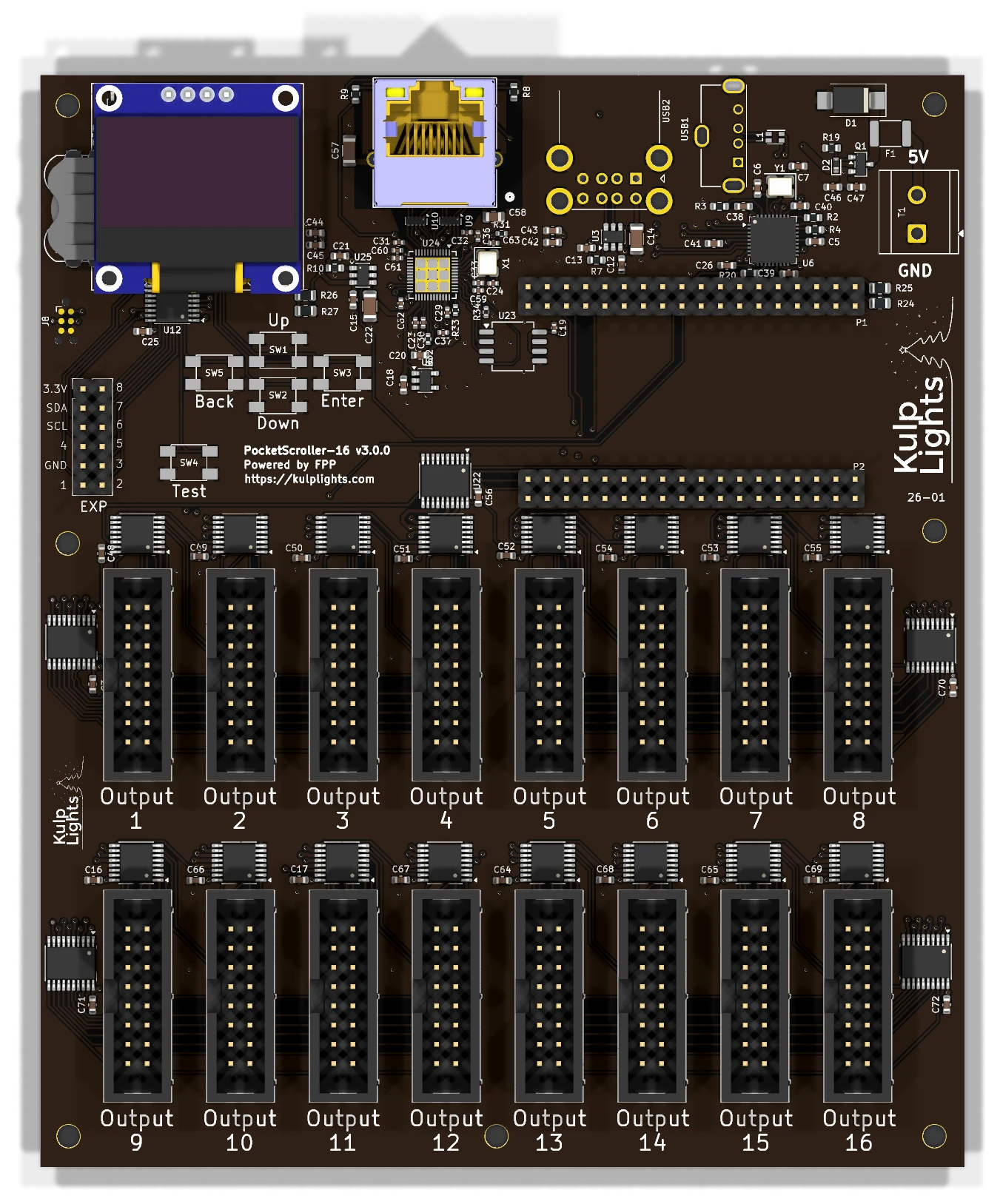
Power¶
5 V only
Like the PocketScroller v3, the PocketScroller-16 has no voltage regulator. Connect a regulated 5 V supply to the terminal marked 5V / GND (top-right corner). A 12 V or 24 V supply makes the protection clamp conduct and trip the resettable fuse, and can damage the board.
- The terminal powers the PocketBeagle 2, the panel drivers, Ethernet and the USB ports, not the panels. The board draws very little, but use a 5 V supply rated 5 A or more: it handles ripple and spikes better.
- Power every panel from your 5 V panel supply. You can feed the PocketScroller-16 from the same supply.
- There are no power LEDs. When the board is running, the OLED shows status.
- FPP shows the input voltage as VIN.
Panel outputs¶
The outputs are in two rows of eight: Output 1–8 across the upper row and Output 9–16 across the lower row, left to right.
Each is marked Output n below its connector, and each is a standard HUB75 connector. The pinout is the same as on the PocketScroller v3.
- Use the ribbon cables that come with your panels. The red stripe goes to pin 1 (marked on the header's shroud).
- Spread the panels evenly across the outputs. The refresh rate depends on the longest chain (see Capacity & refresh rate).
Other connectors¶
| Connector | Marking | Details |
|---|---|---|
| Ethernet | (RJ45 with LEDs) | Network |
| USB-A | — | 3 ports, USB |
| OLED | GND 3.3V SCL SDA |
Controls & display |
| Expansion | EXP |
Expansion header (PocketScroller pinout) |
| RTC battery | coin-cell holder, top-left, behind the OLED | Clock |
Capacity & refresh rate¶
How many panels you can run depends on how long each chain is and on the colour depth. The table gives the full-frame refresh rate in Hz for 64×32 panels at FPP's default brightness (10). Bold values are 60 Hz or more. Italic values are under 60 Hz, where flicker starts to show on camera and to some viewers.
| Panels per output | Total panels | 12-bit | 10-bit | 8-bit | PWM panels (fps) |
|---|---|---|---|---|---|
| 1 | 16 | 174 | 185 | 199 | 306 |
| 2 | 32 | 138 | 152 | 171 | 153 |
| 3 | 48 | 102 | 115 | 130 | 102 |
| 4 | 64 | 83 | 94 | 108 | 76 |
| 5 | 80 | 69 | 78 | 91 | 61 |
| 6 | 96 | 60 | 68 | 80 | 51 |
| 8 | 128 | 50 | 58 | 70 | 38 |
| 10 | 160 | 43 | 51 | 62 | 31 |
| 12 | 192 | 37 | 44 | 54 | 26 |
| 16 | 256 | 29 | 35 | 43 | 19 |
- Rule of thumb at 60 Hz: up to 6 panels per output at 12-bit colour (96 panels), or 10 per output at 8-bit (160 panels).
- Refresh depends only on the longest chain. Every output is clocked whether or not a panel is attached, so using fewer outputs doesn't make it faster. Spread the panels evenly across all 16 outputs.
- 1/8-scan outdoor panels refresh within a few percent of these 1/16-scan figures. Panels with shift-register row drivers ("ABC-shift" addressing, found on some outdoor 1/8 panels) are 7–16 % slower.
- Lowering colour depth is the easiest way to win back refresh on long chains. Lowering the brightness setting raises refresh slightly (about 9 % at brightness 8).
- The brightest bit plane is split into up to four pulses per frame, so the flicker a viewer actually sees runs 2–4× faster than the full-frame figure.
PWM panels¶
Panels with PWM driver chips (FM6363C, FM6353, FM6373) run their own 16-bit greyscale, so they don't flicker as chains get longer. Chain length limits only how many new frames per second reach the panels: the last column of the table. Bold values there meet a 40 fps sequence, which works out to up to 7 panels per output (112 panels). Select the panel's driver chip under Panel Type in FPP's LED Panels settings.
FPP setup¶
When FPP detects the PocketScroller-16 it sets up an LED Panels output (Input/Output Setup → Channel Outputs → LED Panels) with the PocketScroller wiring and a starting layout of 2×2 64×32 panels at low brightness, using all 16 outputs. Set up your panels as described for the PocketScroller v3.
See LED panel matrices in the FPP manual for every field.
Dimensions & mounting¶
- 121.95 × 144.21 mm (4.80 × 5.68 in), 7 plated mounting holes, 3.0 mm, for M2.5 (or #4) screws and standoffs.
- Mounting drawing: PDF.
BeagleBone Black
K8-B¶
A BeagleBone Black pixel controller: 8 fused pixel ports, 3 differential ports and an expansion port for 16 more strings: 36 strings in all.
An early K8-B (v4.0) with a BeagleBone Black fitted. The current board differs in small details; the board map below shows it.
This page describes revision v4.3.1 (printed on the board as K8-B v4.3.1). All the v4.x
boards work the same way: the changes between them were mostly different clock and temperature
chips, used as parts shortages allowed.
How the K8-B differs from the PocketBeagle 2 boards
- It needs a BeagleBone Black (or a compatible BeagleBone). See BeagleBone Black.
- One power terminal, 5–18 V. It powers the controller and all eight ports, so all of them run at the same voltage. Don't use 24 V supplies.
- Mini-blade fuses, not eFuses: no per-port switching or current readings.
- Two DMX outputs on a 6-pin header, not RJ45 jacks.
- The differential ports are send-only. FPP drives this board with its BBB48String output: smart receivers work in v1, v2 or V4 mode. Falcon V5 receivers work in V4 mode, without status reports.
Specifications¶
| K8-B | |
|---|---|
| Local pixel ports | 8 (PT1–PT8), 3-pin 3.5 mm pluggable, plugs included |
| Port protection | 5 A mini-blade fuse per port, with a fuse-OK LED |
| Differential ports | 3 × RJ45 = 12 strings (9–20), send-only |
| Expansion port | 40-pin (2×20) header, 16 strings (21–36), for a Falcon F16v3 expansion board |
| Total strings | 36 |
| Power input | 1 terminal, 5–18 V DC, powers the controller and all 8 ports |
| DMX / serial | 2, RS-485 transmit, on a 2×3 header (ttyS1, ttyS2) |
| Audio | none built in. Use a USB sound card. |
| Ethernet & USB | the BeagleBone's own |
| Display & buttons | 128×64 OLED, Up / Down / Back / Enter / Test, Power |
| Real-time clock | yes, CR1220 backup cell |
| Temperature sensors | 2 (Temp1, Temp2) |
| Size | 86.4 × 108.9 mm (3.40 × 4.29 in), 7 mounting holes, 3.2 mm |
| FPP output | BBB48String |
| Requires | BeagleBone Black or compatible, FPP 9.5 or later |
Board map¶
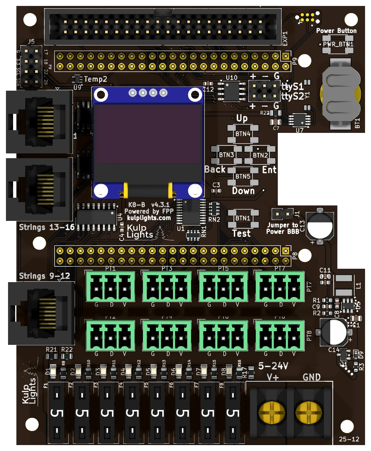
The BeagleBone sits under the upper part of the board, with its Ethernet jack in the notch in the right-hand edge.
Power terminal¶
The K8-B has one power terminal, on the bottom edge to the right of the fuses, marked V+ (left screw) and GND (right screw). It powers the BeagleBone and all of the logic, and every pixel port. FPP shows its voltage as VIN.
- Because every port shares this supply, all eight local strings must be the same voltage: 5 V or 12 V pixels. To mix voltages, put the other strings on differential receivers, which power their strings from their own supply.
- 18 V is the maximum. A 24 V supply will damage the board. (Some boards are printed
5-24V; use 18 V or less anyway.) - The terminal is rated 30 A. With eight ports fused at 5 A, add up your real loads and keep the total under that. Use 10 or 12 AWG wire for heavily loaded boards.
Check polarity before you power up
V+ is the left screw on the K8-B, the opposite of the K8-PB. The BeagleBone and the controller's logic are protected against a reversed supply, but the pixel ports aren't: a reversed supply goes straight through the fuses to every port and to any pixels connected.
See Power for supply sizing and safety.
Powering the BeagleBone: the "Power BBB" jumper¶
The jumper marked Jumper to Power BBB, to the right of the Test button, connects the board's 5 V regulator to the BeagleBone. It is fitted at the factory, and the BeagleBone then runs from the power terminal. Leave it fitted.
With the jumper removed, the BeagleBone isn't powered by the cape, and needs its own 5 V supply in its barrel jack. That isn't recommended. Never fit the jumper and plug a supply into the BeagleBone's barrel jack at the same time.
Pixel ports and fuses¶
The eight pixel ports are in two rows above the fuses:
| Top row | PT1 | PT3 | PT5 | PT7 |
| Bottom row | PT2 | PT4 | PT6 | PT8 |
Each port is G D V (ground, data, +V), as printed beneath it. PT1 is FPP port 1, and so on. See Pixel outputs.
Each port has its own 5 A mini-blade fuse, in a row along the bottom edge: F1 on the left for PT1, to F8 for PT8. The small LED above each fuse lights when the fuse is good and the board has power. An unlit LED means a blown or missing fuse. See Power → Fuses.
Differential ports¶
Three jacks on the left-hand edge, numbered from the bottom up:
| Position | Strings |
|---|---|
| top | 17-20 |
| middle | 13-16 |
| bottom, next to the pixel ports | 9-12 |
Each jack carries four strings. The ports are send-only. Any standard differential receiver works, and smart receivers work in v1, v2 or V4 mode (FPP drives this board with its BBB48String output). Falcon V5 receivers also work, set to V4, but they can't send status back. See Differential ports.
Expansion port (strings 21–36)¶
The 40-pin, 2×20 shrouded header along the top edge carries 16 more pixel data lines. It is compatible with Falcon F16v3 expansion boards, which turn the 16 lines into pixel ports with their own power.
| Pin | Signal | BeagleBone pin | Pin | Signal | BeagleBone pin |
|---|---|---|---|---|---|
| 1 | — | — | 2 | +5 V | — |
| 3 | GND | — | 4 | +5 V | — |
| 5 | GND | — | 6 | String 21 | P8-07 |
| 7 | GND | — | 8 | String 22 | P8-08 |
| 9 | GND | — | 10 | String 23 | P8-09 |
| 11 | GND | — | 12 | String 24 | P8-16 |
| 13 | GND | — | 14 | String 25 | P8-34 |
| 15 | GND | — | 16 | String 26 | P8-36 |
| 17 | GND | — | 18 | String 27 | P8-38 |
| 19 | GND | — | 20 | String 28 | P8-37 |
| 21 | GND | — | 22 | String 29 | P9-12 |
| 23 | GND | — | 24 | String 30 | P9-14 |
| 25 | GND | — | 26 | String 31 | P9-16 |
| 27 | GND | — | 28 | String 32 | P9-15 |
| 29 | GND | — | 30 | — | — |
| 31 | String 33 | P9-23 | 32 | String 34 | P8-11 |
| 33 | GND | — | 34 | String 35 | P8-12 |
| 35 | GND | — | 36 | String 36 | P8-15 |
| 37 | GND | — | 38 | GND | — |
| 39 | +5 V | — | 40 | +5 V | — |
Pin 1 is at the right-hand end of the header, on the outer (board-edge) row. String 33 is on pin 31, not pin 30: that is how the F16v3 expansion connector is laid out.
The data lines can also be used as GPIO inputs, the same way as on the K8-PB: leave a string at 0 pixels and its pin is free for FPP's GPIO Inputs, under the BeagleBone pin name. Wire buttons to switch the pin to GND and use the pull-up mode.
Not for pixels directly
The data lines on this header come straight from the BeagleBone at 3.3 V, with no buffering or protection. Always go through an expansion board, and never connect anything above 3.3 V.
DMX¶
The two DMX outputs share one 2×3 header, to the left of the battery holder, marked ttyS1 (top
row) and ttyS2 (bottom row):
| Row | + (left) |
- (middle) |
G (right) |
|---|---|---|---|
top: ttyS1 |
Data + | Data − | Ground |
bottom: ttyS2 |
Data + | Data − | Ground |
Wire + to XLR pin 3, − to pin 2 and G to pin 1 (or to an RJ45 DMX connector). The
outputs are transmit-only and can also drive Renard, LOR or Pixelnet through a suitable adapter.
FPP calls the ports ttyS1 and ttyS2. See DMX / serial.
Other connectors¶
| Connector | Marking | Details |
|---|---|---|
| OLED | GND VDD SCK SDA |
Controls & display |
| Buttons | Up Down Back Ent, Test |
the four menu buttons, with a separate Test button below them. Controls & display |
| Power button | Power Button |
top right corner. Shuts down or restarts the BeagleBone; see Power button. |
| GPIO / I²C | G 3.3 SCL SDA, P9 17 18 22 26 |
2×4 header, top left corner: 3.3 V, GND, the I²C bus and four BeagleBone pins (P9-17, P9-18, P9-22, P9-26), for extra I²C sensors or buttons to ground. 3.3 V only. |
| RTC battery | coin-cell holder, right edge | Clock |
FPP setup¶
When FPP detects the K8-B it sets itself up automatically. It enables the K8-B pixel-string
layout (FPP's BBB48String output, with all 36 strings: 100 pixels on each local port, none on
the rest), the voltage and temperature sensors, and two disabled DMX outputs on ttyS1 and
ttyS2. Set the pixel counts and start channels from xLights or the FPP Pixel Strings page. See
Configuring outputs.
Dimensions & mounting¶
- 86.36 × 108.86 mm (3.40 × 4.29 in), 7 plated mounting holes, 3.2 mm, for M3 (or #4) screws and standoffs: four in the corners, and three that line up with the BeagleBone's own holes.
- The BeagleBone hangs underneath the K8-B, so the standoffs in the corner holes must be tall enough to clear it and its connectors.
K8-B-Scroller¶
Pixels and LED panels from one BeagleBone Black: 8 fused pixel ports, a differential port for 4 more strings, and 3 HUB75 outputs for LED panels.
K8-B-Scroller (v1.1.0), shown without a BeagleBone fitted.
This page describes revision v1.1.0 (printed on the board as K8-B-Scroller v1.1.0). See
Board revisions for the earlier v1.0.
How the K8-B-Scroller differs from the other boards
- It needs a BeagleBone Black (or a compatible BeagleBone). See BeagleBone Black.
- One power terminal, 5–18 V. It powers the controller and all eight pixel ports, so all of them run at the same voltage. Don't use 24 V supplies. The panels need their own 5 V supply.
- Mini-blade fuses, not eFuses: no per-port switching or current readings.
- Two DMX outputs on a 6-pin header, not RJ45 jacks.
- The differential port is send-only: smart receivers work in v1, v2 or V4 mode. Falcon V5 receivers work in V4 mode, without status reports.
Specifications¶
| K8-B-Scroller | |
|---|---|
| Local pixel ports | 8 (PT1–PT8), 3-pin 3.5 mm pluggable, plugs included |
| Port protection | 5 A mini-blade fuse per port, with a fuse-OK LED |
| Differential ports | 1 × RJ45 = 4 strings (9–12), send-only |
| LED panel outputs | 3 × HUB75 (Panel 1–Panel 3), with E line |
| Power input | 1 terminal, 5–18 V DC, powers the controller and all 8 pixel ports |
| DMX / serial | 2, RS-485 transmit, on a 2×3 header (ttyS1, ttyS2) |
| Audio | none built in. Use a USB sound card. |
| Ethernet & USB | the BeagleBone's own |
| Display & buttons | 128×64 OLED, Up / Down / Back / Enter / Test, Power |
| Real-time clock | yes, CR1220 backup cell |
| Temperature sensor | yes |
| Size | 86.4 × 108.9 mm (3.40 × 4.29 in), 7 mounting holes, 3.2 mm |
| FPP output | BBB48String (pixels), LED Panels (panels) |
| Requires | BeagleBone Black or compatible, FPP 9.5 or later |
Board map¶
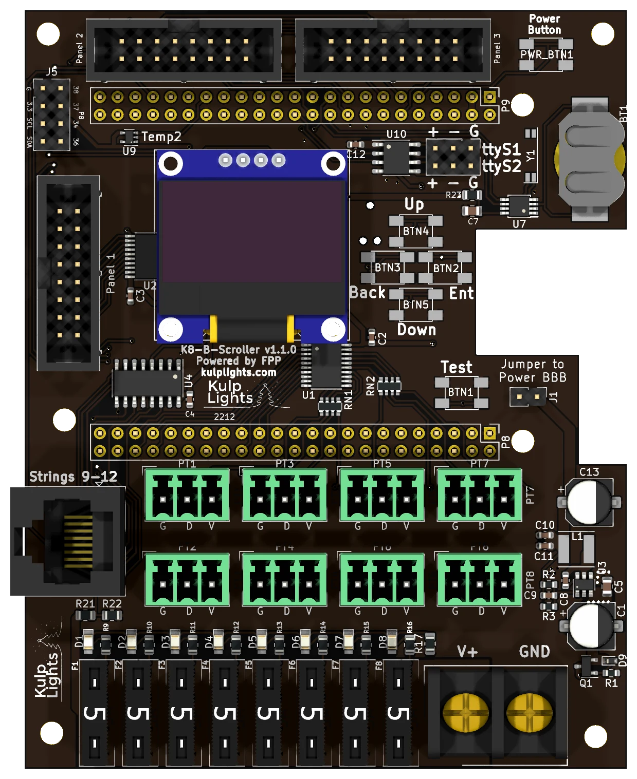
The BeagleBone sits under the upper part of the board, with its Ethernet jack in the notch in the right-hand edge.
Power terminal¶
The power terminal is at the bottom right, marked V+ (left screw) and GND (right screw). It powers the BeagleBone and all of the logic, and every pixel port. FPP shows its voltage as VIN.
- Because every pixel port shares this supply, all eight local strings must be the same voltage: 5 V or 12 V pixels. To mix voltages, put the other strings on a differential receiver, which powers its strings from its own supply.
- 18 V is the maximum. A 24 V supply will damage the board.
- The panels are not powered through the board. Run each panel's power from your 5 V panel supply.
Check polarity before you power up
V+ is the left screw. The BeagleBone and the controller's logic are protected against a reversed supply, but the pixel ports aren't: a reversed supply goes straight through the fuses to every port and to any pixels connected.
See Power for supply sizing and safety.
Powering the BeagleBone: the "Power BBB" jumper¶
The jumper marked Jumper to Power BBB, to the right of the Test button, connects the board's 5 V regulator to the BeagleBone. It is fitted at the factory, and the BeagleBone then runs from the power terminal. Leave it fitted.
With the jumper removed, the BeagleBone isn't powered by the cape, and needs its own 5 V supply in its barrel jack. That isn't recommended. Never fit the jumper and plug a supply into the BeagleBone's barrel jack at the same time.
Pixel ports and fuses¶
The eight pixel ports are in two rows above the fuses:
| Top row | PT1 | PT3 | PT5 | PT7 |
| Bottom row | PT2 | PT4 | PT6 | PT8 |
Each port is G D V (ground, data, +V), as printed beneath it. PT1 is FPP port 1, and so on. See Pixel outputs.
Each port has its own 5 A mini-blade fuse, in a row along the bottom edge: F1 on the left for PT1, to F8 for PT8. The small LED above each fuse lights when the fuse is good and the board has power. An unlit LED means a blown or missing fuse.
Differential port¶
The RJ45 jack on the left-hand edge, marked Strings 9-12, carries strings 9–12. It is send-only.
Any standard differential receiver works, and smart receivers work in v1, v2 or V4 mode (FPP
drives this board with its BBB48String output). Falcon V5 receivers also work, set to V4, but
they can't send status back. See Differential ports.
Panel outputs¶
The three HUB75 outputs are marked Panel 1 (on the left-hand edge) and Panel 2 and Panel 3 (along the top edge, left to right). Each is a standard HUB75 connector:
| Pin | Signal | Pin | Signal |
|---|---|---|---|
| 1 | R1 | 2 | G1 |
| 3 | B1 | 4 | GND |
| 5 | R2 | 6 | G2 |
| 7 | B2 | 8 | E |
| 9 | A | 10 | B |
| 11 | C | 12 | D |
| 13 | CLK | 14 | LAT |
| 15 | OE | 16 | GND |
- The E line is wired, so 1/32-scan panels (such as 64×64) work.
- Use the ribbon cables that come with your panels. The red stripe goes to pin 1 (marked on the header's shroud).
- Each output drives up to about 5 P5 (64×32) or 10 P10 (32×16) panels: 15 P5 or 30 P10 panels in all. The refresh rate depends on the longest chain, so spread the panels evenly.
DMX¶
The two DMX outputs share one 2×3 header, left of the battery holder, marked ttyS1 (top row) and
ttyS2 (bottom row):
| Row | + (left) |
- (middle) |
G (right) |
|---|---|---|---|
top: ttyS1 |
Data + | Data − | Ground |
bottom: ttyS2 |
Data + | Data − | Ground |
Wire + to XLR pin 3, − to pin 2 and G to pin 1 (or to an RJ45 DMX connector). The outputs are transmit-only and can also drive Renard, LOR or Pixelnet through a suitable adapter. See DMX / serial.
Other connectors¶
| Connector | Marking | Details |
|---|---|---|
| OLED | GND VDD SCK SDA |
Controls & display |
| Buttons | Up Down Back Ent, Test |
the four menu buttons, with a separate Test button below them. Controls & display |
| Power button | Power Button |
top right corner. Shuts down or restarts the BeagleBone; see Power button. |
| GPIO / I²C | G 3.3 SCL SDA, P8 38 37 34 36 |
2×4 header, top left corner: 3.3 V, GND, the I²C bus and four BeagleBone pins (P8-34, P8-36, P8-37, P8-38), for extra I²C sensors or buttons to ground. 3.3 V only. |
| RTC battery | coin-cell holder, right edge | Clock |
FPP setup¶
When FPP detects the K8-B-Scroller it sets itself up automatically:
- The K8-B-Scroller pixel-string layout (FPP's BBB48String output), with 12 strings of 100 pixels.
- An LED Panels output with one 64×32 panel on Panel 1.
- The voltage and temperature sensors, and two disabled DMX outputs on
ttyS1andttyS2.
Both outputs start at channel 1, so set the start channels so the strings and the panels don't overlap. Set the panel size, layout and colour depth under Input/Output Setup → Channel Outputs → LED Panels; see LED panel matrices in the FPP manual. For the pixel strings see Configuring outputs.
Board revisions¶
| Revision | Changes |
|---|---|
| v1.0 | Two power terminals: Pixel Power for the pixel ports, and a separate BBB 5V terminal for a 5 V supply that powers the BeagleBone. |
| v1.1 | One power terminal for everything, with a 5 V regulator on the board and the Power BBB jumper. |
Dimensions & mounting¶
- 86.36 × 108.86 mm (3.40 × 4.29 in), 7 plated mounting holes, 3.2 mm, for M3 (or #4) screws and standoffs.
- The BeagleBone hangs underneath the board, so the standoffs in the corner holes must be tall enough to clear it and its connectors.
K64D-B¶
Sixty-four pixel strings from sixteen differential ports, for driving differential receivers, plus two DMX/LOR outputs, built-in audio and an FM transmitter socket. It has no local pixel ports.
K64D-B (v1.0) with a BeagleBone Black fitted upside down.
This page describes revision v1.0 (printed on the board as K64D-B v1.0), the only revision.
How the K64D-B differs from the other boards
- It needs a BeagleBone Black (or a compatible BeagleBone), which plugs in upside down on top of the cape. See BeagleBone Black.
- Differential ports only. Every string goes out over an RJ45 to a differential receiver, which powers the pixels. There are no pixel plugs on the board.
- 5 V only. The board takes a regulated 5 V supply for the controller alone.
- The differential ports are send-only: smart receivers work in v1, v2 or V4 mode. Falcon V5 receivers work in V4 mode, without status reports.
Specifications¶
| K64D-B | |
|---|---|
| Local pixel ports | none |
| Differential ports | 16 × RJ45 = 64 strings (1–64), send-only |
| Power input | 5 V DC only, 2-pin 5.08 mm screw terminal (controller only) |
| DMX / serial | 2, RS-485 transmit, on RJ45 jacks with a DMX/LOR switch (ttyS1, ttyS2) |
| Audio | built-in stereo DAC, 3.5 mm line out, FM transmitter socket |
| GPIO header | 2×8: 3.3 V, 5 V, GND, I²C and 8 BeagleBone pins |
| Ethernet & USB | the BeagleBone's own |
| Display & buttons | 128×64 OLED, Up / Down / Back / Enter / Test, Boot, Power |
| Real-time clock | yes, CR1220 backup cell |
| Temperature sensors | 2 (Temp1, Temp2) |
| Size | 182.0 × 159.6 mm (7.17 × 6.28 in), 7 mounting holes, 3.2 mm |
| FPP output | BBShiftString |
| Requires | BeagleBone Black or compatible, FPP 9.5 or later |
Board map¶
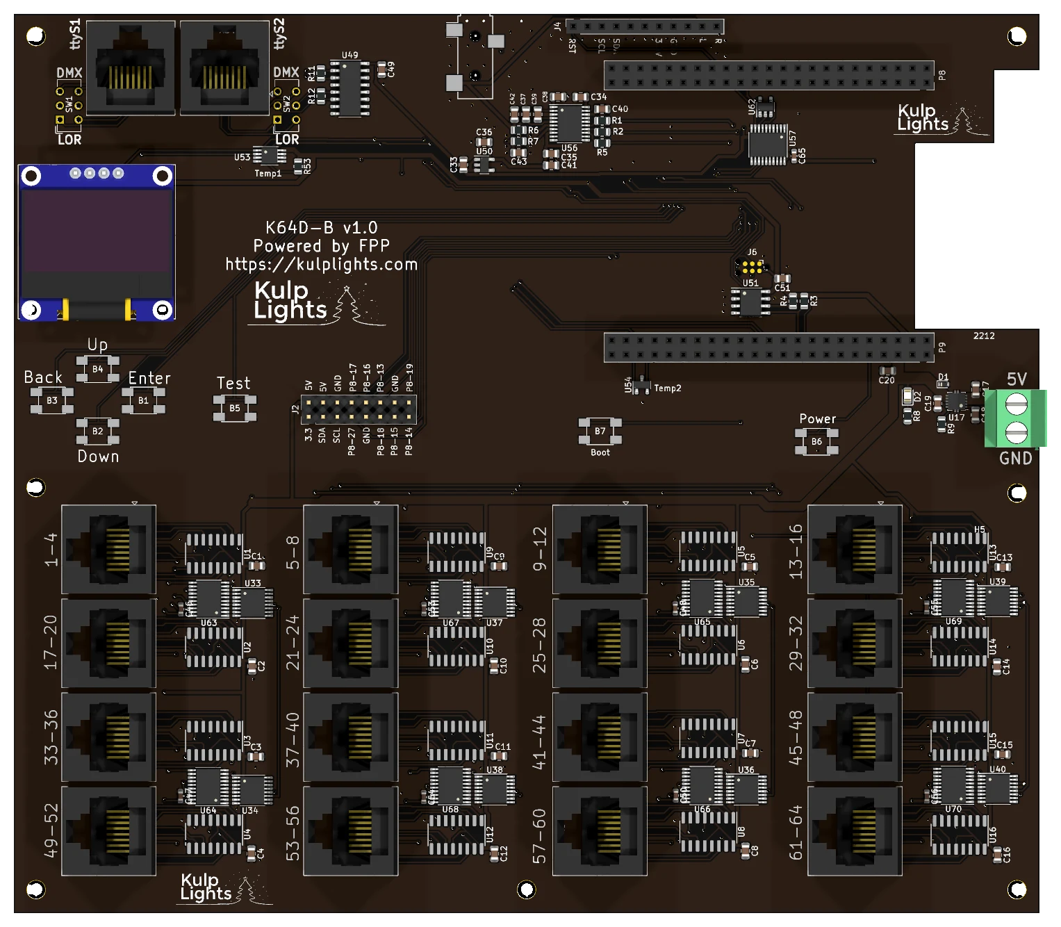
The BeagleBone mounts upside down over the two long headers at the top right, with its Ethernet jack over the notch in the right-hand edge.
Power¶
The power terminal is on the right-hand edge, below the BeagleBone, marked 5V (upper screw) and GND (lower screw). It powers the BeagleBone and all of the logic, including the sixteen differential driver chips. The receivers power the pixels from their own supplies. Use a regulated 5 V supply rated at least 3 A. The LED beside the terminal lights when the board has power. FPP shows no input voltage reading on this board.
5 V only, and check the polarity
Use a regulated 5 V supply. The input is protected against over-voltage and overload, but not against a reversed supply: check that 5 V goes to the upper screw before you switch on. Don't connect 12 V or 24 V.
Differential ports¶
The sixteen jacks are in a 4 × 4 grid on the lower part of the board. Each carries four strings, numbered as printed beside it, across each row and then down:
| Row 1 (top) | 1-4 |
5-8 |
9-12 |
13-16 |
| Row 2 | 17-20 |
21-24 |
25-28 |
29-32 |
| Row 3 | 33-36 |
37-40 |
41-44 |
45-48 |
| Row 4 (bottom) | 49-52 |
53-56 |
57-60 |
61-64 |
The ports are send-only, with the standard four-strings-per-RJ45 pinout. Any standard differential receiver works, and smart receivers work in v1, v2 or V4 mode; with v2 you can chain up to six receivers on a port. Falcon V5 receivers also work, set to V4, but they can't send status back. See Differential ports.
Each string can drive up to 800 pixels at 40 fps, or 1600 at 20 fps. All the strings are sent together, so the longest string sets the frame rate for the whole board.
DMX / LOR¶
The two serial outputs are RJ45 jacks at the top-left corner: ttyS1 on the left and ttyS2 on
the right. Each has a small slide switch beside it:
| Switch | RJ45 pins | Use |
|---|---|---|
| DMX (up) | Data + on pin 1, Data − on pin 2, ground on 7 and 8 | DMX over RJ45, Renard, Pixelnet |
| LOR (down) | Data + on pin 4, Data − on pin 5, ground on 7 and 8 | Light-O-Rama networks: plug straight into LOR controllers |
The outputs are transmit-only. FPP calls them ttyS1 and ttyS2. See
DMX / serial.
Audio and FM transmitter¶
The board has a built-in PCM5102A stereo DAC. Its 3.5 mm line-out jack is on the top edge,
and the FM transmitter socket (RST … L R) is beside it, for an optional Si4713 module. See
Audio.
GPIO header¶
The 2×8 header beside the Test button brings out power, the I²C bus and eight BeagleBone pins, for extra buttons, switches or I²C sensors:
| Pin | Signal | Pin | Signal |
|---|---|---|---|
| 1 | 3.3 V | 2 | 5 V |
| 3 | SDA | 4 | 5 V |
| 5 | SCL | 6 | GND |
| 7 | P8-27 | 8 | P8-17 |
| 9 | GND | 10 | P8-16 |
| 11 | P8-18 | 12 | P8-13 |
| 13 | P8-15 | 14 | GND |
| 15 | P8-14 | 16 | P8-19 |
Pin 1 is at the bottom left; the signal names are printed above and below the pins. Use the pins in FPP's GPIO Inputs, under their BeagleBone names. They connect straight to the BeagleBone, so they are 3.3 V only: wire buttons to switch a pin to GND and use the pull-up mode.
Buttons¶
| Button | Details |
|---|---|
Up Down Back Enter |
the menu buttons, at the left below the OLED. Controls & display |
Test |
to the right of the menu buttons. Test button |
Boot |
below the BeagleBone. Hold it at power-on to boot an older BeagleBone from its SD card; see Booting from the SD card. Pressing it while the board is running briefly glitches strings 9–12 and 25–28. |
Power |
left of the power terminal. Shuts down or restarts the BeagleBone; see Power button. |
Other connectors¶
| Connector | Marking | Details |
|---|---|---|
| OLED | GND VDD SCK SDA |
top left. Controls & display |
| RTC battery | coin-cell holder under the OLED | unplug the OLED to change the cell. Clock |
FPP setup¶
When FPP detects the K64D-B it sets itself up automatically. It enables the K64D-B
pixel-string layout (FPP's BBShiftString output, with all 64 strings at 100 pixels each), the
built-in audio, the temperature sensors, the FM transmitter plugin's settings, and two disabled DMX
outputs on ttyS1 and ttyS2. Set the pixel counts and start channels from xLights or the FPP
Pixel Strings page. See Configuring outputs.
Dimensions & mounting¶
- 182.0 × 159.55 mm (7.17 × 6.28 in), 7 plated mounting holes, 3.2 mm, for M3 (or #4) screws and standoffs.
- Use standoffs at least 6 mm (¼ in) tall, so nothing on the underside touches the enclosure.
K128D-B¶
One hundred and twenty-eight pixel strings from thirty-two differential ports, for driving differential receivers, plus two DMX/LOR outputs, built-in audio and an FM transmitter socket. It has no local pixel ports.
An early K128D-B (v1.0) with a BeagleBone fitted upside down. The current v1.1 has RJ45 jacks for the DMX outputs; the board map below shows it.
This page describes revision v1.1 (printed on the board as K128D-B v1.1). See
Board revisions for v1.0.
How the K128D-B differs from the other boards
- It needs a BeagleBone Black (or a compatible BeagleBone), which plugs in upside down on top of the cape. See BeagleBone Black.
- Differential ports only. Every string goes out over an RJ45 to a differential receiver, which powers the pixels. There are no pixel plugs on the board.
- 5 V only. The board takes a regulated 5 V supply for the controller alone.
- About 80,000 pixels in all. The BeagleBone's processor, not the ports, sets the limit.
- The differential ports are send-only: smart receivers work in v1, v2 or V4 mode. Falcon V5 receivers work in V4 mode, without status reports.
Specifications¶
| K128D-B | |
|---|---|
| Local pixel ports | none |
| Differential ports | 32 × RJ45 = 128 strings (1–128), send-only |
| Pixel capacity | up to 800 per string at 40 fps; about 80,000 in total |
| Power input | 5 V DC only, 2-pin 5.08 mm screw terminal (controller only) |
| DMX / serial | 2, RS-485 transmit, on RJ45 jacks with a DMX/LOR switch (ttyS1, ttyS2) |
| Audio | built-in stereo DAC, 3.5 mm line out, FM transmitter socket |
| GPIO header | 2×8: 3.3 V, 5 V, GND, I²C and 8 BeagleBone pins |
| Ethernet & USB | the BeagleBone's own |
| Display & buttons | 128×64 OLED, Up / Down / Back / Enter / Test, Boot, Power |
| Real-time clock | yes, CR1220 backup cell |
| Temperature sensors | 2 (Temp1, Temp2) |
| Size | 182.0 × 225.0 mm (7.17 × 8.86 in), 7 mounting holes, 3.2 mm |
| FPP output | BBShiftString |
| Requires | BeagleBone Black or compatible, FPP 9.5 or later |
Board map¶
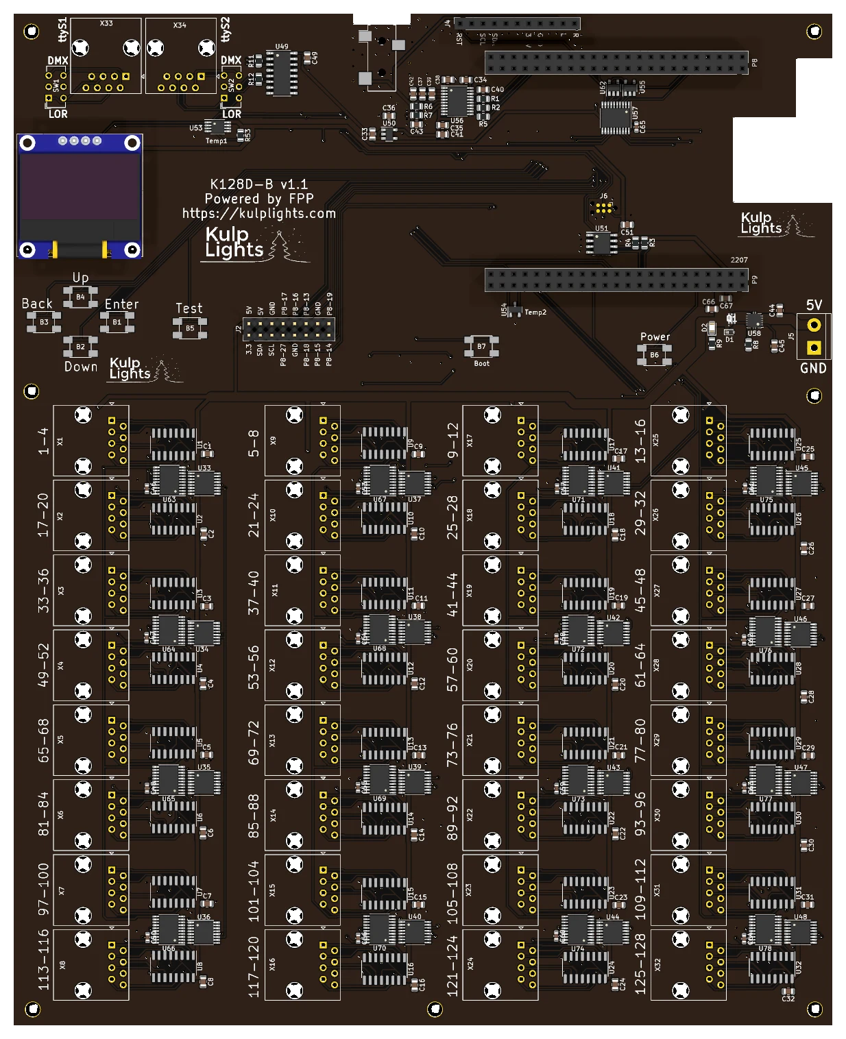
The BeagleBone mounts upside down over the two long headers at the top right, with its Ethernet jack over the notch in the right-hand edge.
Power¶
The power terminal is on the right-hand edge, below the BeagleBone, marked 5V (upper screw) and GND (lower screw). It powers the BeagleBone and all of the logic, including the thirty-two differential driver chips. The receivers power the pixels from their own supplies. Use a regulated 5 V supply rated at least 4 A. The LED beside the terminal lights when the board has power. FPP shows no input voltage reading on this board.
5 V only
Use a regulated 5 V supply, and check that 5 V goes to the upper screw before you switch on. Don't connect 12 V or 24 V.
Differential ports¶
The thirty-two jacks fill the lower part of the board in 8 rows of 4. They are vertical jacks: the cables plug in from above. Each carries four strings, numbered as printed beside it, across each row and then down:
| Row 1 (top) | 1-4 |
5-8 |
9-12 |
13-16 |
| Row 2 | 17-20 |
21-24 |
25-28 |
29-32 |
| Row 3 | 33-36 |
37-40 |
41-44 |
45-48 |
| Row 4 | 49-52 |
53-56 |
57-60 |
61-64 |
| Row 5 | 65-68 |
69-72 |
73-76 |
77-80 |
| Row 6 | 81-84 |
85-88 |
89-92 |
93-96 |
| Row 7 | 97-100 |
101-104 |
105-108 |
109-112 |
| Row 8 (bottom) | 113-116 |
117-120 |
121-124 |
125-128 |
The ports are send-only, with the standard four-strings-per-RJ45 pinout. Any standard differential receiver works, and smart receivers work in v1, v2 or V4 mode; with v2 you can chain up to six receivers on a port. Falcon V5 receivers also work, set to V4, but they can't send status back. See Differential ports.
Pixel capacity¶
Each string can drive up to 800 pixels at 40 fps, or 1600 at 20 fps. All the strings are sent together, so the longest string sets the frame rate for the whole board.
The whole board tops out at about 80,000 pixels, because the BeagleBone's single processor prepares every pixel for every frame. Spread them across the ports however you like. Using the built-in audio takes some of that processor time, so the limit is a little lower when FPP plays audio from the board.
DMX / LOR¶
The two serial outputs are RJ45 jacks at the top-left corner: ttyS1 on the left and ttyS2 on
the right. Each has a small slide switch beside it:
| Switch | RJ45 pins | Use |
|---|---|---|
| DMX (up) | Data + on pin 1, Data − on pin 2, ground on 7 and 8 | DMX over RJ45, Renard, Pixelnet |
| LOR (down) | Data + on pin 4, Data − on pin 5, ground on 7 and 8 | Light-O-Rama networks: plug straight into LOR controllers |
The outputs are transmit-only. FPP calls them ttyS1 and ttyS2. See
DMX / serial.
Audio and FM transmitter¶
The board has a built-in PCM5102A stereo DAC. Its 3.5 mm line-out jack is in the notch on
the top edge, and the FM transmitter socket (RST … L R) is beside it, for an optional
Si4713 module. See Audio.
GPIO header¶
The 2×8 header beside the Test button brings out power, the I²C bus and eight BeagleBone pins, for extra buttons, switches or I²C sensors:
| Pin | Signal | Pin | Signal |
|---|---|---|---|
| 1 | 3.3 V | 2 | 5 V |
| 3 | SDA | 4 | 5 V |
| 5 | SCL | 6 | GND |
| 7 | P8-27 | 8 | P8-17 |
| 9 | GND | 10 | P8-16 |
| 11 | P8-18 | 12 | P8-13 |
| 13 | P8-15 | 14 | GND |
| 15 | P8-14 | 16 | P8-19 |
Pin 1 is at the bottom left; the signal names are printed above and below the pins. Use the pins in FPP's GPIO Inputs, under their BeagleBone names. They connect straight to the BeagleBone, so they are 3.3 V only: wire buttons to switch a pin to GND and use the pull-up mode.
Buttons¶
| Button | Details |
|---|---|
Up Down Back Enter |
the menu buttons, at the left below the OLED. Controls & display |
Test |
to the right of the menu buttons. Test button |
Boot |
below the BeagleBone. Hold it at power-on to boot an older BeagleBone from its SD card; see Booting from the SD card. Pressing it while the board is running briefly glitches strings 65–72. |
Power |
left of the power terminal. Shuts down or restarts the BeagleBone; see Power button. |
Other connectors¶
| Connector | Marking | Details |
|---|---|---|
| OLED | GND VDD SCK SDA |
top left. Controls & display |
| RTC battery | coin-cell holder under the OLED | unplug the OLED to change the cell. Clock |
FPP setup¶
When FPP detects the K128D-B it sets itself up automatically. It enables the K128D-B
pixel-string layout (FPP's BBShiftString output, with all 128 strings at 100 pixels each), the
built-in audio, the temperature sensors, the FM transmitter plugin's settings, and two disabled DMX
outputs on ttyS1 and ttyS2. Set the pixel counts and start channels from xLights or the FPP
Pixel Strings page. See Configuring outputs.
Board revisions¶
| Revision | Changes |
|---|---|
| v1.0 | The two DMX outputs are 3-pin pluggable terminals (G - +), with no DMX/LOR switch, and the differential jacks are surface-mount parts. |
| v1.1 | DMX outputs on RJ45 jacks with DMX/LOR switches, sturdier through-hole differential jacks, and an electronic fuse on the power input. |
Dimensions & mounting¶
- 182.0 × 225.0 mm (7.17 × 8.86 in), 7 plated mounting holes, 3.2 mm, for M3 (or #4) screws and standoffs.
- Use standoffs at least 6 mm (¼ in) tall, so nothing on the underside touches the enclosure.
OctoPlus¶
Eight HUB75 outputs for LED panel matrices on a BeagleBone Black: an updated version of the classic "Octoscroller" cape, with a clock, a temperature sensor, an OLED and buttons.
An early OctoPlus (v2.2), without the OLED fitted. The board map below shows the current board.
This page describes revision v2.3.1 (printed on the board as OctoPlus v2.3.1). See
Board revisions for the earlier boards.
How the OctoPlus differs from the other boards
- It needs a BeagleBone Black (or a compatible BeagleBone). See BeagleBone Black.
- 5 V only. The terminal powers the BeagleBone and the cape. The panels need their own 5 V supply.
- No E line, so 1/32-scan panels (such as 64×64 1/32) don't work. 1/16-scan and lower do.
- No mounting holes. The cape is held by its headers on the BeagleBone; mount the BeagleBone.
Specifications¶
| OctoPlus | |
|---|---|
| LED panel outputs | 8 × HUB75 (Output 1–8), no E line |
| Panels | P10 (32×16, 1/4 or 1/8 scan) and P5 (64×32, 1/8 or 1/16 scan), and other 1/16-scan or lower panels |
| Power input | 5 V DC only, 2-pin 3.5 mm screw terminal |
| DMX / serial | none |
| Audio | none built in. Use a USB sound card. |
| Ethernet & USB | the BeagleBone's own |
| Display & buttons | 128×64 OLED, Test-Down / Enter |
| Real-time clock | yes, CR1220 backup cell |
| Temperature sensor | yes |
| Size | 55.4 × 98.6 mm (2.18 × 3.88 in), no mounting holes |
| FPP output | LED Panels (BeagleBone, Octoscroller v2 wiring) |
| Requires | BeagleBone Black or compatible, FPP 9.5 or later |
Board map¶
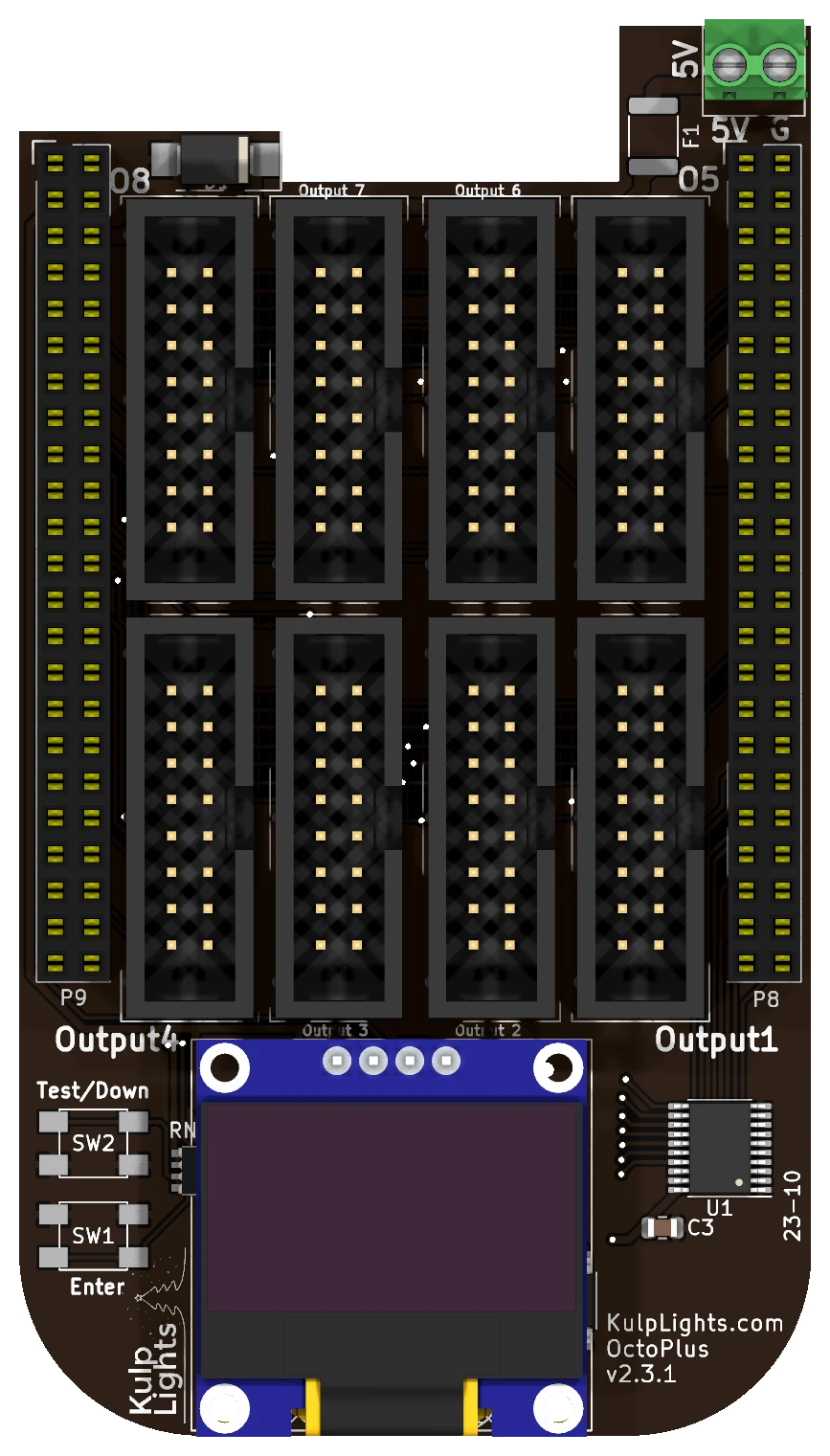
Shown with the BeagleBone's Ethernet jack at the top, in the notch beside the power terminal.
Power¶
The power terminal is on the tab at the top-right corner, marked 5V (left screw) and G (right screw).
- It powers the BeagleBone and the cape. Use a regulated 5 V supply rated at least 2 A, more if you plug anything into the BeagleBone's USB port.
- The panels are not powered through the OctoPlus. Run each panel's power from your 5 V panel supply. You can feed the OctoPlus from the same supply.
- There are no power LEDs. When the board is running, the OLED shows status.
5 V only
The OctoPlus has no voltage regulator. A 12 V or 24 V supply, or a reversed one, makes the protection clamp conduct and trip the resettable fuse, and can damage the board.
Panel outputs¶
The eight outputs are in two rows of four between the BeagleBone's headers. With the Ethernet jack at the top:
| Top row | Output 8 | Output 7 | Output 6 | Output 5 |
| Bottom row | Output 4 | Output 3 | Output 2 | Output 1 |
Each is a standard HUB75 connector, except that pin 8 is ground instead of E:
| Pin | Signal | Pin | Signal |
|---|---|---|---|
| 1 | R1 | 2 | G1 |
| 3 | B1 | 4 | GND |
| 5 | R2 | 6 | G2 |
| 7 | B2 | 8 | GND (no E) |
| 9 | A | 10 | B |
| 11 | C | 12 | D |
| 13 | CLK | 14 | LAT |
| 15 | OE | 16 | GND |
- Use the ribbon cables that come with your panels. The red stripe goes to pin 1 (marked on the header's shroud).
- FPP allows up to 16 panels per output. The refresh rate depends on the longest chain and on the colour depth; see Capacity & refresh rate.
- On a SanCloud BeagleBone Enhanced, Output 5 doesn't work properly.
Other connectors¶
| Connector | Marking | Details |
|---|---|---|
| OLED | GND VDD SCK SDA |
bottom centre. Controls & display |
| Buttons | Test/Down, Enter |
bottom left corner. Controls & display |
| RTC battery | coin-cell holder under the OLED | unplug the OLED to change the cell. Clock |
The OctoPlus has no Power button. Use FPP's Shutdown, then switch off the supply.
Capacity & refresh rate¶
How many panels you can run depends on how long each chain is and on the colour depth. The table gives the full-frame refresh rate in Hz for 64×32 1/16-scan panels with all eight outputs in use, measured on an OctoPlus at FPP's default brightness (10). Bold values are 60 Hz or more. Italic values are under 60 Hz, where flicker starts to show on camera and to some viewers.
| Panels per output | Total panels | 12-bit | 10-bit | 8-bit | 6-bit |
|---|---|---|---|---|---|
| 1 | 8 | 111 | 132 | 212 | 257 |
| 2 | 16 | 79 | 95 | 138 | 177 |
| 3 | 24 | 59.9 | 73 | 99 | 130 |
| 4 | 32 | 48 | 58 | 74 | 96 |
| 5 | 40 | 40 | 48 | 60 | 78 |
| 6 | 48 | 34 | 41 | 50 | 65 |
| 8 | 64 | 26 | 30 | 38 | 49 |
| 10 | 80 | 20 | 24 | 30 | 39 |
| 12 | 96 | 17 | 21 | 26 | 34 |
| 16 | 128 | 13 | 16 | 19 | 26 |
- Rule of thumb at 60 Hz with 64×32 panels: 2–3 panels per output at 12-bit colour, or 5 per output at 8-bit (40 panels).
- Smaller panels go further. A 32×16 P10 panel holds a quarter of the pixels of a 64×32, so a chain of P10s refreshes about as fast as a chain of a quarter as many 64×32s.
- Refresh depends on the longest chain. Spread the panels evenly across the outputs.
- A single chain on Output 1 runs up to twice as fast, because Output 1 shares its I/O bank with the panel control lines. Adding a second output costs most of that gain; going from 2 to 8 outputs costs only another 10–15 %.
- These are worst-case figures, measured with random pixel data. Frames with flat or solid areas refresh faster: a solid fill ran 44 % faster at 3 panels per output, 8-bit.
- 1/8-scan outdoor panels refresh about the same from 4 panels per output up, and faster on shorter chains (158 Hz at 1 panel per output, 12-bit).
- Lowering the colour depth is the easiest way to win back refresh on long chains. Unlike the PocketScroller v3, a lower brightness setting lowers the refresh rate a little on the OctoPlus.
FPP setup¶
When FPP detects the OctoPlus it sets up an LED Panels output (Input/Output Setup → Channel Outputs → LED Panels) with the OctoPlus wiring, starting with one 32×16 1/8-scan panel on Output 1. Change it to match your panels:
- Set the panel size and scan (e.g. 32×16 1/8, 64×32 1/16).
- Set the layout: how many panels wide and high.
- In the grid, assign each panel to an output and a position in the chain, and set its orientation.
- Set colour depth and brightness, then save. FPP restarts the output.
See LED panel matrices in the FPP manual for every field.
Board revisions¶
The revision is printed on the board next to the name. Every revision uses the same FPP setup.
| Revision | Changes |
|---|---|
| v2.2x | The early boards. The panel lines come straight from the BeagleBone. |
| v2.3 | Adds a 5 V buffer for the panels' clock, latch, OE and row-select lines, for more reliable panel driving. |
| v2.3.1 | Current board. |
Dimensions & mounting¶
- 55.37 × 98.55 mm (2.18 × 3.88 in), with a notch for the BeagleBone's Ethernet jack, a tab for the power terminal, and rounded corners at the far end.
- No mounting holes. The OctoPlus is held by its headers on the BeagleBone, so mount the BeagleBone by its own holes.
K16A-B¶
The K16A-B was a BeagleBone Black pixel controller: 16 pixel ports, 4 differential ports and an expansion port, for 48 strings in all, plus audio and two DMX outputs.
K16A-B v3.0, powered, with a BeagleBone Black fitted.
Retired
The K16A-B is no longer sold. This page is for the many boards still in use. Its successors are the PocketBeagle 2 K16, K16-Pro and K16-Max.
The K16A-B went through three generations. They share the layout, connectors and FPP setup, but
differ in power and port protection, so check which one you have. The revision is printed on the
board, under the name (K16A-B v3.0.1).
| Generation | Revisions | Made | Power terminals | Port protection |
|---|---|---|---|---|
| v1 | v1.0.0 – v1.2 | 2020–2022 | 2 | 5 A mini-blade fuses |
| v2 | v2.0, v2.1 | 2023–2024 | 2 | eFuses, about 5.2 A |
| v3 | v3.0, v3.0.1 | 2024–2025 | 4 | eFuses, about 6 A |
How the K16A-B differs from the PocketBeagle 2 boards
- It needs a BeagleBone Black (or a compatible BeagleBone). See BeagleBone Black.
- The power terminals don't all have the same polarity. Check the markings on each one.
- Only one terminal runs the controller: the right-hand one.
Specifications¶
| v1 | v2 | v3 | |
|---|---|---|---|
| Local pixel ports | 16, 3-pin 3.5 mm pluggable | 16 | 16 |
| Port protection | 5 A mini-blade fuse per port | eFuse per port, about 5.2 A, latching | eFuse per port, about 6 A, latching |
| Power switching & current readings | — | per port | per port |
| Power terminals | 2 (ports 1–8, 9–16) | 2 (ports 1–8, 9–16) | 4 (one per 4 ports) |
| Voltage | 5 or 12 V, 12 V max | 5–18 V | 5–24 V |
| Differential ports | 4 × RJ45 = 16 strings (17–32), send-only | 4 × RJ45, two-way on the first pair | 4 × RJ45, two-way on the first pair |
| Falcon V5 receivers | V4 mode | yes, with an updated cape EEPROM | yes |
| Expansion port | 40-pin, F16v3-style, strings 33–48 | 24-pin, F16v4-style, strings 33–48 | 24-pin, F16v4-style |
| DMX / serial | 2, on 3-pin terminals | 2, on RJ45 jacks | 2, on RJ45 jacks |
| Audio | stereo DAC, 3.5 mm line out, FM transmitter socket | same | same |
| Display & buttons | 128×64 OLED, Up / Down / Back / Enter / Test, Power | same | same |
| Real-time clock | yes, CR1220 cell | yes | yes |
| FPP output | BBB48String | BBShiftString | BBShiftString |
| Size | 150.0 × 113.9 mm (5.90 × 4.48 in) | same | same, 10 mounting holes |
All three need a BeagleBone Black or compatible and run on FPP 9.5 or later.
Board map¶
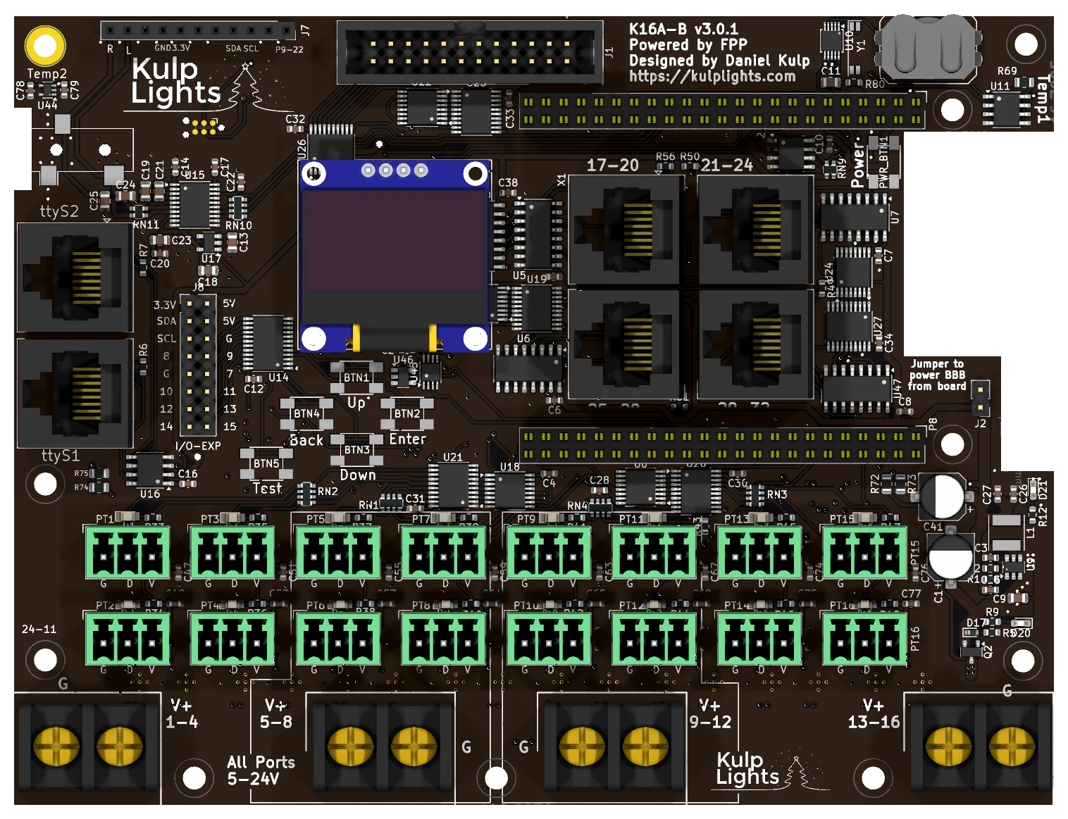
v3.0.1. The v1 and v2 boards have the same layout above the pixel ports; below them they have two power terminals with the fuses (v1) between them.
The BeagleBone sits underneath the board, with its Ethernet jack in the notch in the right-hand edge.
Power¶
Four terminals along the bottom edge, one per bank of four ports. The polarity alternates from one terminal to the next:
| Terminal | Marking | Left screw | Right screw | Powers |
|---|---|---|---|---|
| 1st (left) | V+ 1-4 |
G | V+ | ports 1–4 |
| 2nd | V+ 5-8 |
V+ | G | ports 5–8 |
| 3rd | V+ 9-12 |
G | V+ | ports 9–12 |
| 4th (right) | V+ 13-16 |
V+ | G | ports 13–16, and the BeagleBone and all the logic |
- The board won't start without power on the right-hand
V+ 13-16terminal, even with the others powered. - Each bank can run its own voltage, 5–24 V, so 5, 12 and 24 V pixels can share the board on different banks.
- FPP shows the four voltages as VIN1–VIN4. Two blue LEDs on the right-hand edge show that the right-hand terminal has power and that the 5 V supply is running.
- Only the controller's own supply (the right-hand terminal) is protected against a reversed supply. A reversed supply on any terminal can damage that bank's ports.
Two terminals along the bottom edge:
| Terminal | Left screw | Right screw | Powers |
|---|---|---|---|
| left | G | V+ | ports 1–8 |
| right | V+ | G | ports 9–16, and the BeagleBone and all the logic |
- The board won't start without power on the right-hand terminal.
- Each terminal can run its own voltage, 5–18 V. Don't use 24 V supplies.
- FPP shows the two voltages as VIN1 and VIN2.
- The controller's own supply is protected against a reversed supply; the pixel ports aren't.
Two terminals along the bottom edge, with the fuses between them:
| Terminal | Left screw | Right screw | Powers |
|---|---|---|---|
| left | G | V+ | ports 1–8 |
| right | V+ | G | ports 9–16, and the BeagleBone and all the logic |
- 5 V or 12 V only, 12 V maximum. Don't use 24 V supplies.
- The 3-pin Input Voltage Select jumper must match the supply on the right-hand terminal: 5V for a 5 V supply, 12V for 12 V.
- The board won't start without power on the right-hand terminal.
- FPP shows the two voltages as VIN1 and VIN2.
- The pixel ports aren't protected against a reversed supply. Check the polarity of each terminal before you power up.
See Power for supply sizing and safety.
Powering the BeagleBone: the "power BBB" jumper¶
The jumper marked Jumper to power BBB from board, on the right-hand side, connects the board's 5 V supply to the BeagleBone. It is fitted at the factory; leave it fitted. With it removed, the BeagleBone needs its own supply in its barrel jack. Never fit the jumper and plug a supply into the BeagleBone's barrel jack at the same time.
Pixel ports¶
The sixteen pixel ports are in two rows across the lower part of the board:
| Top row | PT1 | PT3 | PT5 | PT7 | PT9 | PT11 | PT13 | PT15 |
| Bottom row | PT2 | PT4 | PT6 | PT8 | PT10 | PT12 | PT14 | PT16 |
Each port is G D V (ground, data, +V), as printed beneath it. PT1 is FPP port 1, and so on. On v1 boards the bottom row is offset half a step to the right. Each port can drive up to 800 pixels at 40 fps. See Pixel outputs.
Every port has its own eFuse, which trips at about 6 A (v3) or 5.2 A (v2) and latches off. FPP reads every port's current and switches each port on and off as needed. When an eFuse trips, FPP marks the port with a red icon on Status/Control → Port Status; click it to turn the port back on once the fault is fixed. The LED by each port lights when the port has power. See Current monitoring.
Each port has its own 5 A mini-blade fuse, in a row along the bottom edge. The LED by each fuse lights when the fuse is good and the bank has power. See Power → Fuses.
Differential ports¶
The four jacks are in a 2 × 2 block in the upper middle of the board, numbered across the top row and then the bottom row:
| left | right | |
|---|---|---|
| Top | 17-20 |
21-24 |
| Bottom | 25-28 |
29-32 |
Each jack carries four strings, with the standard pinout. See Differential ports.
- v1: send-only. Smart receivers work in v1, v2 or V4 mode; Falcon V5 receivers work set to V4, without status reports.
- v2 and v3: the first pair of each jack is two-way, so Falcon V5 receivers can report back. On v2, that needs a cape EEPROM from April 2024 or later: update it under Help → About → Cape Info (see Updating). v3 boards have it already.
Expansion port (strings 33–48)¶
The 24-pin, 2×12 shrouded header on the top edge carries 16 more pixel strings, for a Falcon F16v4-style expansion board, which turns them into pixel ports with their own power. The pinout is the same as the K8-PB's: GND on pins 1, 2 and 22, +5 V on 3 and 4, and strings 33–48 on pins 5–20 in order (string 33 on pin 5, 34 on pin 6, and so on). Pin 1 is at the right-hand end, on the outer (board-edge) row.
The lines are driven at 5 V by the board's shift registers, so they can't be used as GPIO inputs.
The 40-pin, 2×20 header on the top edge carries 16 more pixel strings, for a Falcon F16v3 expansion board. The pinout is the same as the K8-B's, with strings 33–48 in place of 21–36. The lines come straight from the BeagleBone at 3.3 V: always go through an expansion board.
DMX¶
Two RJ45 jacks on the left-hand edge: ttyS2 above ttyS1. Each is wired for DMX over RJ45:
| RJ45 pin | Signal | DMX XLR pin |
|---|---|---|
| 1 | Data + | 3 |
| 2 | Data − | 2 |
| 7, 8 | Ground | 1 |
There is no LOR setting: use an adapter for LOR, Renard or Pixelnet. See DMX / serial.
Two 3-pin pluggable terminals on the left-hand edge: ttyS1 above ttyS2 (the other way
round from v2 and v3). From top to bottom each is Data +, Data −, Ground. Wire them
to XLR pins 3, 2 and 1. See DMX / serial.
The outputs are transmit-only. FPP sets up a disabled DMX output on each.
Audio and FM transmitter¶
The built-in PCM5102A stereo DAC drives the 3.5 mm line-out jack at the top-left corner. The
11-pin FM transmitter socket along the top edge (R L GND 3.3V SDA SCL P9-22) takes the optional
Si4713 FM transmitter. See
Audio.
Other connectors¶
| Connector | Marking | Details |
|---|---|---|
| OLED | GND VDD SCK SDA |
Controls & display |
| Buttons | Up Down Back Enter, Test |
the menu buttons in a diamond below the OLED, with Test to their lower left. Controls & display |
| Power button | Power |
upper right. Shuts down or restarts the BeagleBone; see Power button. There is no Boot button: use the BeagleBone's own. |
| GPIO / I²C | I/O-EXP |
2×8 header left of the OLED: 3.3 V, 5 V, GND, the I²C bus and nine spare lines on the button I/O expander, numbered 7–15 on the board. FPP lists them in GPIO Inputs as pca9675-7 to pca9675-15. They are 3.3 V, pull up weakly and can only sink current: use them for switches to ground. |
| RTC battery | coin-cell holder, top right | Clock |
FPP setup¶
When FPP detects the K16A-B it sets itself up from the board's EEPROM: the K16A-B pixel-string
layout (100 pixels on each local port), the built-in audio, the sensors, the FM transmitter plugin's
settings, and two disabled DMX outputs on ttyS1 and ttyS2. v1 boards use FPP's BBB48String
output; v2 and v3 use BBShiftString. Set the pixel counts and start channels from xLights or the
FPP Pixel Strings page. See Configuring outputs.
Board revisions¶
| Revision | Changes |
|---|---|
| v1.0.0 | First release: 2 terminals, mini-blade fuses, Input Voltage Select jumper, 40-pin expansion header, DMX on 3-pin terminals. |
| v1.0.1 | Over-voltage and over-current protection on the controller's supply. |
| v1.1 | Different clock, temperature and regulator chips, as parts shortages allowed. |
| v1.2 | Reverse-polarity protection on the controller's supply. |
| v2.0 | eFuses with per-port switching and current readings, shift-register outputs, 24-pin expansion header, DMX on RJ45 jacks, two-way differential ports. |
| v2.1 | A wiring fix on the 17-20 jack. |
| v3.0, v3.0.1 | Four power terminals (one per bank of four), 6 A eFuses, 5–24 V, four voltage readings, three more mounting holes. |
Dimensions & mounting¶
- 149.99 × 113.86 mm (5.90 × 4.48 in), plated 3.2 mm mounting holes for M3 (or #4) screws: 7 on v1 and v2, 10 on v3.
- The BeagleBone hangs underneath the board, so the standoffs must be tall enough to clear it and its connectors.
- A printable mount for v3 boards is on Printables.
K32A-B¶
The K32A-B was a BeagleBone Black pixel controller: 32 fused pixel ports and 4 differential ports, for 48 strings in all, plus audio and two DMX outputs.
An early K32A-B (v1.0.0) with a BeagleBone Black fitted underneath. The current board differs in small details; the board map below shows it.
Retired
The K32A-B is no longer sold. This page is for the many boards still in use. Its successors are the PocketBeagle 2 K32, K32-Pro and K32-Max.
This page describes revision v1.3.1 (printed on the board as K32A-B v1.3.1), and notes where
earlier boards differ. See Board revisions.
How the K32A-B differs from the PocketBeagle 2 boards
- It needs a BeagleBone Black (or a compatible BeagleBone). See BeagleBone Black.
- Four power terminals, one per bank of eight ports. Only the bottom-right one runs the controller.
- Boards before v1.3 have an Input Voltage Select jumper and take 5 or 12 V only.
- The differential ports are send-only: smart receivers work in v1, v2 or V4 mode.
Specifications¶
| K32A-B | |
|---|---|
| Local pixel ports | 32 (PT1–PT32), 3-pin 3.5 mm pluggable |
| Port protection | 5 A mini-blade fuse per port, with a fuse-OK LED |
| Differential ports | 4 × RJ45 = 16 strings (33–48), send-only |
| Total strings | 48 |
| Power terminals | 4, one per bank of 8 ports |
| Voltage | v1.3 and later: 5–18 V. Earlier: 5 or 12 V, 12 V max. |
| DMX / serial | 2, RS-485 transmit, on 3-pin pluggable terminals (ttyS1, ttyS2) |
| Audio | stereo DAC, 3.5 mm line out, FM transmitter socket |
| Expansion port | none |
| Display & buttons | 128×64 OLED, Up / Down / Back / Enter / Test, Power |
| Real-time clock | yes, CR1220 backup cell |
| Temperature sensors | 2 (Temp1, Temp2) |
| Size | 149.9 × 149.9 mm (5.90 × 5.90 in), 9 mounting holes, 3.2 mm |
| FPP output | BBB48String |
| Requires | BeagleBone Black or compatible, FPP 9.5 or later |
Board map¶
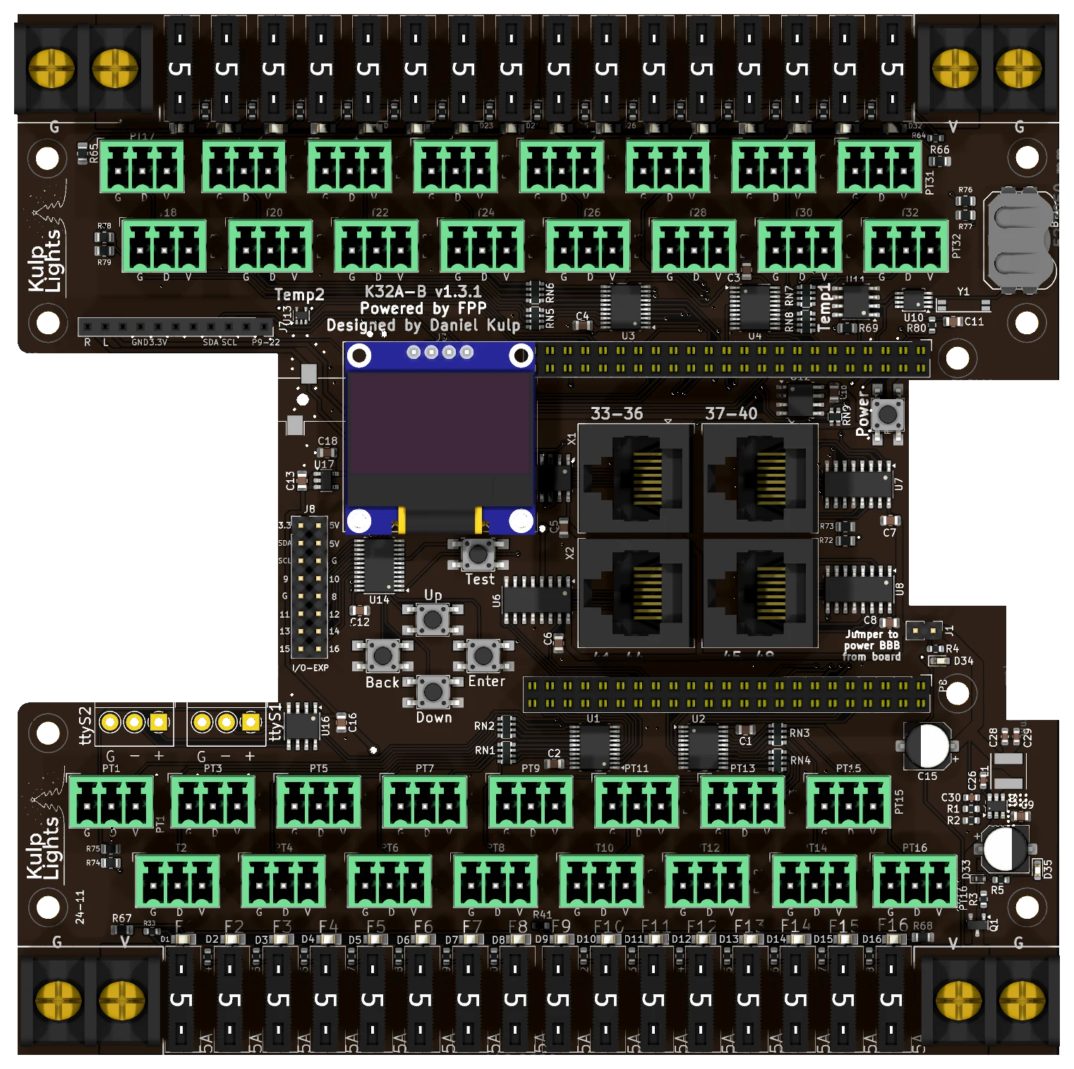
The BeagleBone sits underneath the middle of the board, with its Ethernet jack in the notch in the right-hand edge.
Power¶
Four terminals, one in each corner. Each powers one bank of eight ports through their fuses. On every terminal G is the outer screw, nearer the corner, and V+ the inner one.
| Terminal | Marking | Powers |
|---|---|---|
| bottom left | G V |
ports 1–8 |
| bottom right | V G |
ports 9–16, and the BeagleBone and all the logic |
| top left | G V |
ports 17–24 |
| top right | V G |
ports 25–32 |
- The board won't start without power on the bottom-right terminal, even with the others powered.
- Each bank can run its own voltage, so 5 and 12 V pixels can share the board on different banks.
- v1.3 and later: 5–18 V on any terminal. Don't use 24 V supplies.
- Before v1.3: 5 or 12 V only, 12 V maximum. The 3-pin Input Voltage Select jumper, at the lower right, must match the supply on the bottom-right terminal: 5V for 5 V, 12V for 12 V.
- FPP shows the four voltages as VIN1 (ports 1–8), VIN2 (9–16), VIN3 (17–24) and VIN4 (25–32).
- On v1.3.1 two blue LEDs on the right-hand side show that the bottom-right terminal has power and that the 5 V supply is running.
- The terminals are rated 30 A. Use 10 or 12 AWG wire for heavily loaded banks.
Check polarity before you power up
The pixel ports aren't protected against a reversed supply: it goes straight through the fuses to that bank's ports and any pixels connected. From v1.3 the controller itself is protected.
See Power for supply sizing and safety.
Powering the BeagleBone: the "power BBB" jumper¶
The jumper marked Jumper to power BBB from board, on the right-hand side above the BeagleBone's Ethernet jack, connects the board's 5 V supply to the BeagleBone. It is fitted at the factory; leave it fitted. With it removed, the BeagleBone needs its own supply in its barrel jack. Never fit the jumper and plug a supply into the BeagleBone's barrel jack at the same time.
Pixel ports and fuses¶
The ports are in two blocks of sixteen, with the fuses along the outer edges. In each block the two rows are offset half a step:
| Row | Ports, left to right |
|---|---|
| top block, outer row | PT17 · PT19 · PT21 · PT23 · PT25 · PT27 · PT29 · PT31 |
| top block, inner row | PT18 · PT20 · PT22 · PT24 · PT26 · PT28 · PT30 · PT32 |
| bottom block, inner row | PT1 · PT3 · PT5 · PT7 · PT9 · PT11 · PT13 · PT15 |
| bottom block, outer row | PT2 · PT4 · PT6 · PT8 · PT10 · PT12 · PT14 · PT16 |
Each port is G D V (ground, data, +V), as printed beneath it. PT1 is FPP port 1, and so on. Each port can drive up to 800 pixels at 40 fps. See Pixel outputs.
Each port has its own 5 A mini-blade fuse: F1–F16 along the bottom edge and F17–F32 along the top, left to right. The LED beside each fuse lights when the fuse is good and the bank has power. See Power → Fuses.
Differential ports¶
The four jacks are in a 2 × 2 block in the middle of the board:
| left | right | |
|---|---|---|
| Top | 33-36 |
37-40 |
| Bottom | 41-44 |
45-48 |
Each jack carries four strings, with the standard pinout. The ports are send-only. Any standard differential receiver works, and smart receivers work in v1, v2 or V4 mode. Falcon V5 receivers also work, set to V4, but they can't send status back. See Differential ports.
DMX¶
The two DMX outputs are 3-pin pluggable terminals at the left, just above the bottom block of pixel
ports: ttyS2 on the left, ttyS1 on the right. Each is marked G − +, left to right:
G |
− |
+ |
|---|---|---|
| Ground (XLR pin 1) | Data − (XLR pin 2) | Data + (XLR pin 3) |
The outputs are transmit-only and can also drive Renard, LOR or Pixelnet through a suitable adapter. FPP sets up a disabled DMX output on each. See DMX / serial.
Audio and FM transmitter¶
The built-in PCM5102A stereo DAC drives the 3.5 mm line-out jack, which opens into the notch
in the left-hand edge. The 11-pin FM transmitter socket below the top block of ports
(R L GND 3.3V SDA SCL P9-22) takes the optional
Si4713 FM transmitter. See
Audio.
Other connectors¶
| Connector | Marking | Details |
|---|---|---|
| OLED | GND VDD SCK SDA |
Controls & display |
| Buttons | Up Down Back Enter, Test |
the menu buttons in a cross below the OLED, with Test above them to the right. Controls & display |
| Power button | Power |
right-hand side, above the Ethernet notch. Shuts down or restarts the BeagleBone; see Power button. There is no Boot button: use the BeagleBone's own. |
| GPIO / I²C | I/O-EXP |
2×8 header left of the buttons: 3.3 V, 5 V, GND, the I²C bus and nine spare lines on the button I/O expander, numbered 8–16 on the board. FPP lists them in GPIO Inputs as pca9675-7 to pca9675-15 (one lower than the board's numbers). They are 3.3 V, pull up weakly and can only sink current: use them for switches to ground. |
| RTC battery | coin-cell holder, top right | Clock |
FPP setup¶
When FPP detects the K32A-B it sets itself up from the board's EEPROM: the K32A-B pixel-string
layout (FPP's BBB48String output, with 100 pixels on each local port and none on the
differential ports), the built-in audio, the voltage and temperature sensors, the FM transmitter
plugin's settings, and two disabled DMX outputs on ttyS1 and ttyS2. Set the pixel counts and
start channels from xLights or the FPP Pixel Strings page. See
Configuring outputs.
Board revisions¶
| Revision | Changes |
|---|---|
| v1.0.0 | First release. Input Voltage Select jumper (5V / 12V). |
| v1.1.0, v1.1.1 | Over-voltage and over-current protection on the controller's supply. |
| v1.2 | Different regulator, clock and temperature chips, as parts shortages allowed. Still has the Input Voltage Select jumper. |
| v1.3 | Input Voltage Select jumper removed: a fixed 5 V regulator with reverse-polarity protection, 5–18 V. |
| v1.3.1 | Adds the two blue power LEDs. |
Dimensions & mounting¶
- 149.86 × 149.86 mm (5.90 × 5.90 in), 9 plated mounting holes, 3.2 mm, for M3 (or #4) screws.
- The BeagleBone hangs underneath the board, so the standoffs must be tall enough to clear it and its connectors.
Raspberry Pi
K8-Pi¶
A Raspberry Pi pixel controller: 8 eFused pixel ports with per-port current monitoring, 3 differential ports and an expansion port for 16 more strings: 36 strings in all.
K8-Pi (v2.0) on a Raspberry Pi 4.
This page describes revision v2.0.3 (printed on the board as K8-Pi v2.0.3). See
Board revisions for the earlier boards, including the v1.0 with fuses.
How the K8-Pi differs from the other boards
- It needs a Raspberry Pi 3 B+, 4 or 5. See Raspberry Pi.
- One power terminal, 5–18 V. It powers the Pi and all eight ports, so all of them run at the same voltage. Don't use 24 V supplies.
- One DMX output on a 3-pin header, not an RJ45 jack.
- The differential ports are send-only, and smart receivers work in v1 or v2 mode only.
Specifications¶
| K8-Pi | |
|---|---|
| Local pixel ports | 8 (PT1–PT8), 3-pin 3.5 mm pluggable, plugs included |
| Port protection | eFuse per port, about 5.2 A, latching |
| Power switching | per port (FPP-controlled) |
| Current monitoring | every local port |
| Differential ports | 3 × RJ45 = 12 strings (9–20), send-only |
| Expansion port | 40-pin (2×20) header, 16 strings (21–36), for a Falcon F16v3 expansion board |
| Total strings | 36 |
| Pixels per string | up to 1600; about 800 at 40 fps |
| Power input | 1 terminal, 5–18 V DC, powers the Pi and all 8 ports |
| DMX / serial | 1, RS-485 transmit, 3-pin 2.54 mm header (ttyAMA0) |
| Audio | the Pi's own |
| Ethernet & USB | the Pi's own |
| Display & buttons | 128×64 OLED, Up / Down / Back / Enter / Test |
| Real-time clock | yes, CR1220 backup cell |
| Temperature sensor | yes |
| Size | 97.5 × 105.7 mm (3.84 × 4.16 in), 4 mounting holes for the Pi + 4 for the enclosure |
| FPP output | DPIPixels |
| Requires | Raspberry Pi 3 B+, 4 or 5, FPP 10 or later |
Board map¶
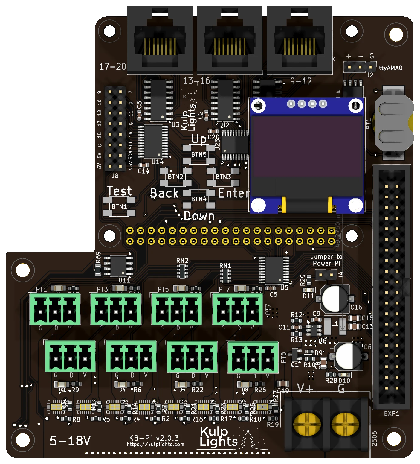
The Pi sits under the upper part of the board, with its USB and Ethernet ports in the cut-out at the top left.
Power terminal¶
The K8-Pi has one power terminal, at the bottom right, marked V+ (left screw) and G (right screw). It powers the Pi and all of the logic, and every pixel port. FPP shows its voltage as VIN.
- Because every port shares this supply, all eight local strings must be the same voltage: 5 V or 12 V pixels. To mix voltages, put the other strings on differential receivers, which power their strings from their own supply.
- 18 V is the maximum. A 24 V supply will damage the board.
- With a 5 V supply, turn its output up to about 5.3 V so the Pi gets a full 5 V; see Raspberry Pi → Powering.
- Two blue LEDs show power: one near the terminal lights when the terminal has power, and one beside the Jumper to Power Pi when the Pi's 5 V supply is on.
Check polarity before you power up
The Pi and the controller's logic are protected against a reversed supply, but the pixel ports aren't: a reversed supply reaches the eFuses and the ports directly and can damage them. Check that V+ goes to the left screw before you switch on.
See Power for supply sizing and safety.
Powering the Pi: the "Power Pi" jumper¶
The jumper marked Jumper to Power Pi, above the power terminal, connects the board's 5 V regulator to the Pi. It is fitted at the factory, and the Pi then runs from the power terminal.
You can instead remove the jumper and power the Pi from its own USB power supply; the board's logic then runs from the Pi, and the ports still need the power terminal. Never fit the jumper and plug in the Pi's own power supply at the same time.
Pixel ports¶
The eight pixel ports are in two rows across the lower half of the board:
| Top row | PT1 | PT3 | PT5 | PT7 |
| Bottom row | PT2 | PT4 | PT6 | PT8 |
Each port is G D V (ground, data, +V), as printed beneath it. PT1 is FPP port 1, and so on. Each string can have up to 1600 pixels; the longest string sets the frame rate, about 40 fps at 800 pixels. See Pixel outputs and Raspberry Pi → Pixel outputs.
eFuses and current monitoring¶
Every local port has its own eFuse, which trips at about 5.2 A, and FPP reads every port's current. FPP turns each port on and off as needed. When an eFuse trips, FPP switches the port off and marks it with a red icon on Status/Control → Port Status. Click the icon to turn the port back on once the fault is fixed. The LED by each port lights when the port has power. See Current monitoring.
Differential ports¶
17-20 · 13-16 · 9-12, from left to right along the top edge.
Each jack carries four strings, numbered as printed beside it. The ports are send-only. Any standard differential receiver works, and smart receivers work in v1 or v2 mode. See Differential ports.
Expansion port (strings 21–36)¶
The 40-pin, 2×20 shrouded header on the right-hand edge carries 16 more pixel strings. It is compatible with Falcon F16v3 expansion boards, which turn them into pixel ports with their own power.
The expansion strings share their data lines with ports 1–16: FPP sends both sets of data down the same lines, and latch signals on pins 2 and 4 tell the K8-Pi and the expansion board which set is theirs. That's how the F16v3 expansion connector is designed. Because of the sharing, the expansion lines can't be used as GPIO inputs.
| Pin | Signal | Pin | Signal |
|---|---|---|---|
| 1 | — | 2 | latch |
| 3 | GND | 4 | latch |
| 5 | GND | 6 | String 21 |
| 7 | GND | 8 | String 22 |
| 9 | GND | 10 | String 23 |
| 11 | GND | 12 | String 24 |
| 13 | GND | 14 | String 25 |
| 15 | GND | 16 | String 26 |
| 17 | GND | 18 | String 27 |
| 19 | GND | 20 | String 28 |
| 21 | GND | 22 | String 29 |
| 23 | GND | 24 | String 30 |
| 25 | GND | 26 | String 31 |
| 27 | GND | 28 | String 32 |
| 29 | GND | 30 | — |
| 31 | String 33 | 32 | String 34 |
| 33 | GND | 34 | String 35 |
| 35 | GND | 36 | String 36 |
| 37 | GND | 38 | GND |
| 39 | +5 V | 40 | +5 V |
Not for pixels directly
The data lines on this header come straight from the Pi at 3.3 V, with no buffering or protection. Always go through an expansion board.
DMX¶
DMX is on the 3-pin, 2.54 mm header at the top right, marked ttyAMA0:
+ (left) |
- (middle) |
G (right) |
|---|---|---|
| Data + | Data − | Ground |
Wire + to XLR pin 3, − to pin 2 and G to pin 1 (or to an RJ45 DMX connector). The output
is transmit-only and can also drive Renard, LOR or Pixelnet through a suitable adapter. FPP calls the
port ttyAMA0. See DMX / serial.
Other connectors¶
| Connector | Marking | Details |
|---|---|---|
| OLED | GND VDD SCK SDA |
Controls & display |
| Buttons | Up Down Back Enter, Test |
the four menu buttons in a diamond, with a separate Test button to their left. Controls & display |
| GPIO / I²C | 3.3V 5V SDA SCL GND, 7–15 |
2×8 header, top left: power, the I²C bus and nine spare lines on the button I/O expander, which FPP lists as GPIO-7 to GPIO-15. Like the Exp header lines they are 3.3 V, pull up weakly and can only sink current: use them for switches to ground. |
| RTC battery | coin-cell holder, top right | Clock |
FPP setup¶
When FPP detects the K8-Pi it sets itself up automatically. It enables the K8-Pi pixel-string
layout (FPP's DPIPixels output, with 100 pixels on each local and differential string and none
on the expansion strings), the voltage, current and temperature sensors, and a disabled DMX output
on ttyAMA0. Set the pixel counts and start channels from xLights or the FPP Pixel Strings page.
See Configuring outputs.
On a Pi 5, use FPP 10.1 or later and keep the cape EEPROM up to date (Help → About → Cape Info), so the K8-Pi's clock is used instead of the Pi 5's own.
Board revisions¶
The revision is printed on the board next to the name.
| Revision | Changes |
|---|---|
| v1.0 | Mini-blade fuses (5 A) instead of eFuses: no per-port switching or current readings. Everything else works the same. |
| v2.0, v2.0.1 | eFuses with per-port switching and current readings. These eFuses retry automatically after a trip; FPP still switches a faulted port off and warns. |
| v2.0.2, v2.0.3 | The eFuses latch off after a trip until FPP turns the port back on. v2.0.3 adds the 5-18V marking. |
Dimensions & mounting¶
- 97.54 × 105.66 mm (3.84 × 4.16 in), L-shaped, with a cut-out for the Pi's USB and Ethernet ports.
- 4 × 2.7 mm holes (M2.5) match the Pi's mounting holes: fix the K8-Pi to the Pi with M2.5 standoffs.
- 4 × 3.2 mm plated holes (M3) at the corners for mounting in an enclosure, on standoffs tall enough to clear the Pi underneath.
K2-Pi-Servo¶
Two eFused pixel ports and 16 servo outputs on a Raspberry Pi hat, for props that move as well as light up.
K2-Pi-Servo (v1.0).
This page describes revision v1.0 (printed on the board as K2-Pi-Servo v1.0), the only
revision.
How the K2-Pi-Servo differs from the other boards
- It needs a Raspberry Pi 3 B+, 4 or 5. See Raspberry Pi.
- Two power terminals: one (5–24 V) for the Pi and the two pixel ports, and a separate one for the servos. The two terminals have their screws in the opposite order.
- No differential ports, DMX or real-time clock.
Specifications¶
| K2-Pi-Servo | |
|---|---|
| Local pixel ports | 2 (Port 1, Port 2), 3-pin 3.5 mm pluggable, plugs included |
| Port protection | eFuse per port, about 6 A, latching |
| Power switching | per port (FPP-controlled) |
| Current monitoring | both ports |
| Pixels per string | up to 1600; about 800 at 40 fps |
| Servo outputs | 16, standard 3-pin servo headers (signal, V+, GND) |
| Power inputs | pixels & Pi: 5–24 V DC. Servos: separate terminal, typically 5–6 V. |
| DMX / serial | none |
| Audio | the Pi's own |
| Ethernet & USB | the Pi's own |
| Display & buttons | 128×64 OLED, Up / Down / Back / Enter / Test |
| Real-time clock | none |
| Temperature sensor | yes |
| Size | 76.4 × 56.0 mm (3.01 × 2.20 in), 4 mounting holes, 2.7 mm |
| FPP output | DPIPixels (pixels), Servos (PCA9685) |
| Requires | Raspberry Pi 3 B+, 4 or 5, FPP 10 or later |
Board map¶
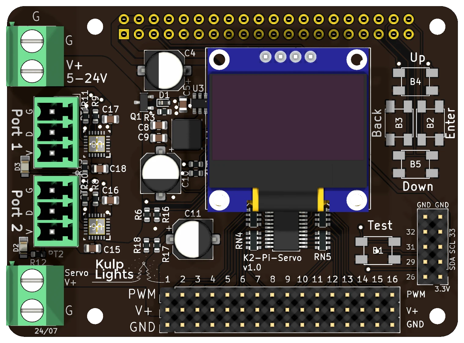
The Pi sits under the board, with its USB and Ethernet ports sticking out past the right-hand edge. The terminals and pixel ports overhang the other end of the Pi.
Power terminals¶
There are two power terminals on the left-hand edge:
| Terminal | Marking | Screws, top to bottom | Powers |
|---|---|---|---|
| Pixel / Pi (top left) | G, V+ 5-24V |
G, then V+ | the Pi, the board's logic and both pixel ports |
| Servo (bottom left) | Servo V+, G |
V+, then G | the 16 servos' V+ pins only |
The two terminals are wired in opposite order
On the top terminal G is the upper screw; on the servo terminal V+ is the upper screw. Check each one against the markings before you power up.
Pixel / Pi terminal:
- The pixels run at the supply voltage, so both strings must match it: 5, 12 or 24 V.
- With a 5 V supply, turn its output up to about 5.3 V so the Pi gets a full 5 V; see Raspberry Pi → Powering.
- The Pi and the logic are protected against a reversed supply, but the pixel ports aren't.
- FPP shows its voltage as VIN Pixel.
Servo terminal:
- Connect a supply that matches your servos, typically 5–6 V, sized for all the servos moving at once. The Pi and the pixels don't need it.
- It goes straight to the servo headers, with no fuse and no reverse-polarity protection. A reversed supply reaches every servo.
- FPP shows its voltage as VIN Servo.
Pixel ports¶
The two pixel ports are on the left-hand edge between the terminals: Port 1 above Port 2. Each is G D V from top to bottom (ground, data, +V). Each string can have up to 1600 pixels; see Raspberry Pi → Pixel outputs.
Each port has its own eFuse, which trips at about 6 A and latches off, and FPP reads both ports' current. When an eFuse trips, FPP marks the port with a red icon on Status/Control → Port Status; click it to turn the port back on once the fault is fixed. The green LED beside each port lights when the port has power. See Current monitoring.
Servo outputs¶
The 16 servo outputs are three rows of pins along the bottom edge, numbered 1 to 16 from left to right. Each column is one servo:
| Row | Marking | Servo wire |
|---|---|---|
| top (yellow) | PWM |
signal (yellow, orange or white) |
| middle (red) | V+ |
power (red) |
| bottom (black) | GND |
ground (black or brown) |
Plug each servo in with its signal wire towards the top of the board. The signal is 5 V.
Set the servos up in FPP under Input/Output Setup → Channel Outputs → Servos. For each output you set its start channel, its minimum and maximum pulse width (500–2500 µs; the default 1000–2000 µs suits most servos), and what it does when its channel is zero (hold, go to the minimum, maximum or centre, or stop). The frequency (50 Hz by default) applies to all 16. The Servo Position command moves a servo from a playlist, a button or a schedule. The outputs can also dim small LEDs instead of driving servos.
Other connectors¶
| Connector | Marking | Details |
|---|---|---|
| OLED | GND VDD SCK SDA |
Controls & display |
| Buttons | Up Down Back Enter, Test |
the menu buttons in a cross at the right, with Test below them. Controls & display |
| GPIO / I²C | GND GND, 3.3V SDA SCL, 26 29 31 32 33 |
2×5 header, bottom right: ground, 3.3 V, the I²C bus (for an add-on clock or sensor) and five Pi GPIO pins, numbered by their Pi header pin. Use them in FPP's GPIO Inputs. 3.3 V only: wire buttons to switch a pin to GND. |
The board has no real-time clock: set up NTP under Settings → Time, or add an I²C clock module on the GPIO / I²C header.
FPP setup¶
When FPP detects the K2-Pi-Servo it sets itself up automatically. It enables the K2-Pi-Servo pixel-string layout (FPP's DPIPixels output, with 100 pixels on each port), the Servos output, and the voltage, current and temperature sensors. Set the pixel counts and start channels from xLights or the FPP Pixel Strings page. See Configuring outputs.
Dimensions & mounting¶
- 76.43 × 56.00 mm (3.01 × 2.20 in), 4 holes, 2.7 mm, for M2.5 screws. They line up with the Pi's mounting holes: fix the board to the Pi with M2.5 standoffs, nylon or metal.
- The board is a little longer than the Pi: the terminals and pixel ports overhang the end opposite the Pi's USB ports.
K2-Pi0¶
The smallest controller: two eFused pixel ports with current monitoring, on a hat the size of a Raspberry Pi Zero.
K2-Pi0 (v1.0).
This page describes revision v1.0 (printed on the board as K2-Pi0 v1.0), the only revision.
How the K2-Pi0 differs from the other boards
- It's made for a Raspberry Pi Zero 2 W. See Raspberry Pi and Fitting it to a Pi.
- No Ethernet: the Pi Zero 2 W has Wi-Fi only.
- No display or buttons, no DMX and no real-time clock. Set it up and control it from FPP's web page.
Specifications¶
| K2-Pi0 | |
|---|---|
| Local pixel ports | 2 (PT1, PT2), 3-pin 3.5 mm pluggable, plugs included |
| Port protection | eFuse per port, about 6 A, latching |
| Power switching | per port (FPP-controlled) |
| Current monitoring | both ports |
| Pixels per string | up to 1600; about 800 at 40 fps |
| Power input | 1 terminal, 5–24 V DC, powers the Pi and both ports |
| DMX / serial | none |
| Network | the Pi's Wi-Fi |
| Display & buttons | none |
| Real-time clock | none |
| Size | 65 × 30 mm (2.56 × 1.18 in), 4 mounting holes, 2.7 mm |
| FPP output | DPIPixels |
| Requires | Raspberry Pi Zero 2 W (see below for other Pis), FPP 10 or later |
Board map¶
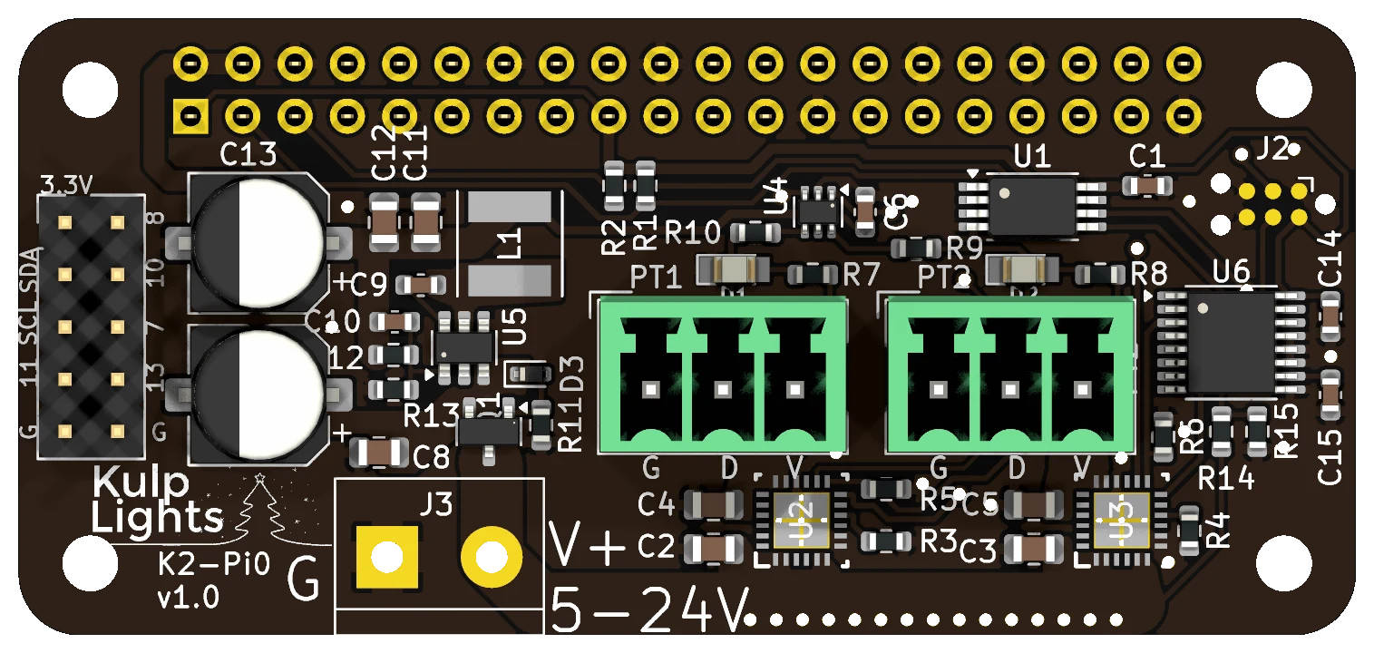
Power terminal¶
The power terminal is at the bottom left, marked G (left screw) and V+ 5-24V (right screw). It powers the Pi and both pixel ports. FPP shows its voltage as VIN.
- The pixels run at the supply voltage, so both strings must match it: 5, 12 or 24 V.
- With a 5 V supply, turn its output up to about 5.3 V so the Pi gets a full 5 V; see Raspberry Pi → Powering.
- The Pi is protected against a reversed supply, but the pixel ports aren't. Check the polarity before you power up.
- Don't plug a supply into the Pi's own USB power socket while the K2-Pi0 is powered.
Pixel ports¶
The two pixel ports, PT1 (left) and PT2 (right), are in the middle of the board. Each is G D V (ground, data, +V), as printed beneath it. Each string can have up to 1600 pixels; see Raspberry Pi → Pixel outputs.
Each port has its own eFuse, which trips at about 6 A and latches off, and FPP reads both ports' current. When an eFuse trips, FPP marks the port with a red icon on Status/Control → Port Status; click it to turn the port back on once the fault is fixed. The green LED beside each port lights when the port has power. See Current monitoring.
GPIO / I²C header¶
The 2×5 header at the left-hand end brings out 3.3 V, ground, the I²C bus and five Pi GPIO pins, numbered on the board by their Pi header pin: 7, 8, 10, 11 and 13. Use them in FPP's GPIO Inputs for buttons or switches to ground, or add an I²C display or clock module. They are 3.3 V only.
Fitting it to a Pi¶
On a Pi Zero 2 W (or Zero W), the K2-Pi0's four holes line up with the Pi's: fix them together with M2.5 standoffs.
It also works on the bigger Pis (3 B+, 4, 5), but there its holes don't line up with anything. The board is held only by the GPIO header, so make sure it can't tip or press down onto the Pi, where it could short something out. Support it with something insulating, and keep it clear of the Pi's components.
FPP setup¶
When FPP detects the K2-Pi0 it sets itself up automatically. It enables the K2-Pi0 pixel-string layout (FPP's DPIPixels output, with 100 pixels on each port) and the voltage and current sensors. Set the pixel counts and start channels from xLights or the FPP Pixel Strings page. See Configuring outputs.
For the first setup, connect to FPP's Wi-Fi hotspot and join the Pi to your Wi-Fi network. Because the board has no clock, set up NTP under Settings → Time so schedules run at the right time.
Dimensions & mounting¶
- 65 × 30 mm (2.56 × 1.18 in), 4 holes, 2.7 mm, for M2.5 screws, on the Pi Zero's hole pattern.
Displays & add-ons
BBB-OLED¶
A small add-on for a plain BeagleBone Black running FPP: an OLED status display, four menu buttons, a real-time clock and a temperature sensor. It has no outputs of its own.
BBB-OLED (v2.0), shown without its display, which covers the clock battery.
This page describes revision v2.0 (printed on the board as BBB-OLED v2.0).
Use it on a BeagleBone that drives its lights over the network or USB, or plays the show as a player or master: it gives the BeagleBone the same display, menus and test buttons as the Kulp controllers. It plugs onto the BeagleBone's P9 header only.
Not with an output cape
The BBB-OLED uses pins on the P9 header that the BeagleBone Black output capes also use. Fit it to a BeagleBone without another cape.
Specifications¶
| BBB-OLED | |
|---|---|
| Display | 128×64 OLED, blue/yellow, fitted |
| Buttons | Up / Down / Back / Enter |
| Real-time clock | yes, CR1220 cell included |
| Temperature sensor | yes |
| Headers | 1×4 I²C socket; 2×5 I²C and GPIO header |
| Outputs | none |
| Power | from the BeagleBone |
| Size | 66.6 × 34.0 mm (2.62 × 1.34 in), no mounting holes |
| Requires | BeagleBone Black or compatible (see BeagleBone Black), FPP 9.5 or later |
Board map¶
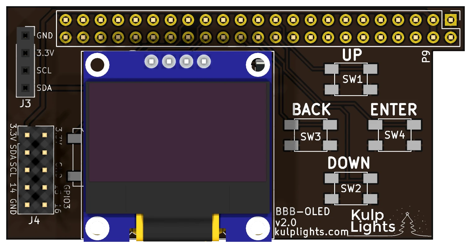
Fitting it¶
- Disconnect power from the BeagleBone.
- Line the BBB-OLED's socket up with the P9 header: the end marked
P9goes at the BeagleBone's Ethernet end, with the board lying over the BeagleBone. - Press it down evenly until it is fully seated. It has no mounting holes; the header holds it.
The BBB-OLED takes its power from the BeagleBone. Power the BeagleBone from its barrel jack or USB as usual.
Buttons¶
The four buttons are in a diamond at the right: UP at the top, BACK at the left, ENTER at the right and DOWN at the bottom. DOWN also works as Test on the status page. See Controls & display.
Clock¶
The real-time clock keeps time with no network. Its CR1220 cell sits under the display: unplug the display to change it. See Clock.
Headers¶
| Header | Marking | Details |
|---|---|---|
| I²C socket | J3: GND 3.3V SCL SDA |
1×4 socket at the top left, on the I²C bus, for an extra I²C sensor or device. |
| GPIO / I²C | J4: 3.3V SDA SCL 14 GND, 3.3V GND GPIO3 15 16 |
2×5 header below it, laid out like the first ten pins of a Raspberry Pi header: 3.3 V, GND, the I²C bus and three BeagleBone GPIOs (GPIO3_14, GPIO3_15 and GPIO3_16, on P9-31, P9-29 and P9-30). Unlike a Pi, it has 3.3 V only, no 5 V: some Pi I²C add-ons work if they run on 3.3 V. |
The GPIO pins are 3.3 V only: use them for buttons or switches to ground in FPP's GPIO Inputs.
FPP setup¶
When FPP detects the BBB-OLED it sets up the display, the buttons, the clock and the temperature sensor automatically.
Board revisions¶
| Revision | Changes |
|---|---|
| v1.0 | No real-time clock. |
| v2.0 | Adds the clock and its battery. |
Pi-OLED¶
An add-on for a Raspberry Pi running FPP: an OLED status display, four menu buttons, a real-time clock and a temperature sensor. It has no outputs of its own. It comes in two versions:
- Pi-OLED 2.0 ("basic"): a narrow board held by the Pi's header.
- PiOLED 3.0 With Audio: a full-size Pi hat that adds a high-quality audio output.
Use it on a Pi that drives its lights over the network or USB, or plays the show as a player or master: it gives the Pi the same display, menus and buttons as the Kulp controllers.
Not with an output hat
The Pi-OLED uses GPIO pins that the Kulp Pi controllers also use. Fit it to a Pi without another hat.
Specifications¶
| Pi-OLED 2.0 | PiOLED 3.0 With Audio | |
|---|---|---|
| Display | 128×64 OLED, blue/yellow, fitted | same |
| Buttons | Up / Down / Back / Enter | same |
| Real-time clock | yes, CR1220 cell included | same |
| Temperature sensor | yes | yes |
| Audio | — | stereo DAC, 3.5 mm line out |
| Headers | 1×4 I²C socket; 2×5 Pi pins 1–10 | 2×5 Pi pins 1–10 |
| Outputs | none | none |
| Power | from the Pi | from the Pi |
| Size | 62.0 × 33.9 mm (2.44 × 1.34 in), no mounting holes | 65 × 56 mm (2.56 × 2.20 in), 4 holes on the Pi's pattern |
| Raspberry Pi | 3 B+, 4, 5, Zero 2 W | 3 B+, 4, 5 |
| FPP | 9.5 or later | 10.1 or later |
Pi-OLED 2.0¶
Pi-OLED v2.0. The current board is printed Pi-OLED v2.0.1.
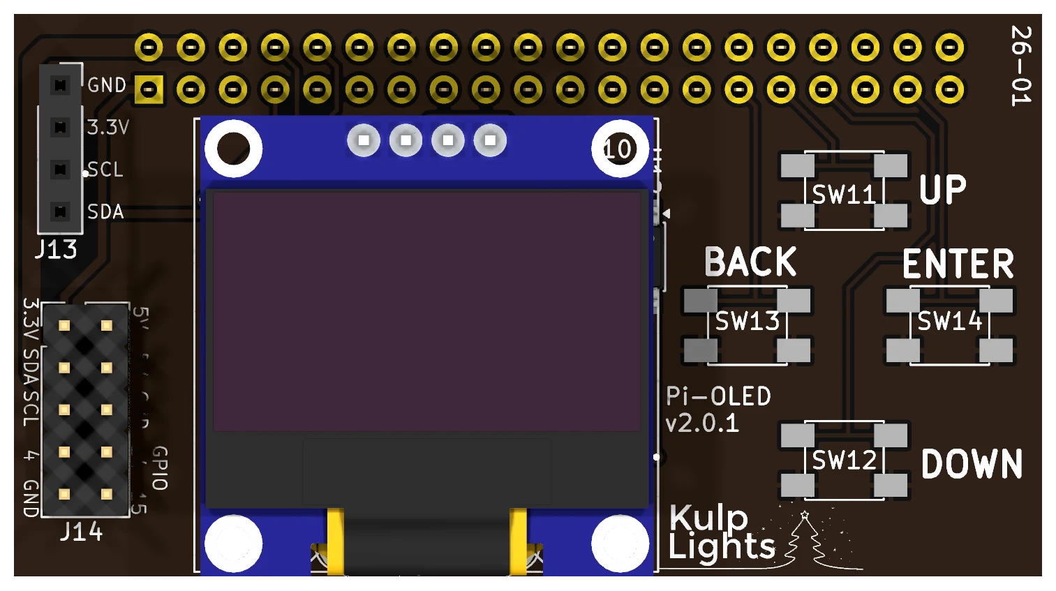
- Fitting: disconnect power, then press its socket onto the Pi's 40-pin header, with the board lying over the Pi. It has no mounting holes; the header holds it.
- Buttons: in a diamond at the right: UP at the top, BACK at the left, ENTER at the right and DOWN at the bottom. See Controls & display.
- Clock: the CR1220 cell sits under the display: unplug the display to change it.
- Headers at the left:
| Header | Marking | Details |
|---|---|---|
| I²C socket | J13: GND 3.3V SCL SDA |
1×4 socket on the I²C bus, for an extra I²C sensor or device. |
| Pi pins 1–10 | J14: 3.3V SDA SCL 4 GND, 5V 5V GND GPIO 14 15 |
2×5 header that repeats the first ten pins of the Pi's header: 3.3 V, 5 V, GND, the I²C bus and GPIO 4, 14 and 15. Add-ons that plug onto those ten pins, such as some clock modules, work here. |
PiOLED 3.0 With Audio¶
PiOLED 3.0 With Audio.
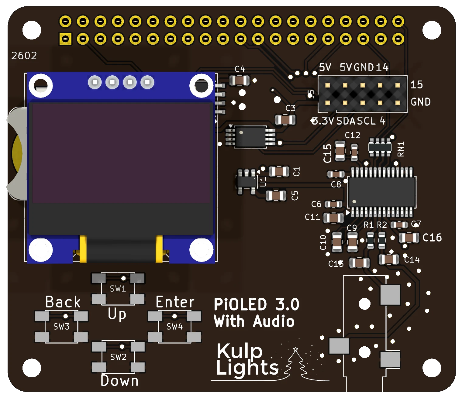
- Fitting: a standard Pi hat. Fit it on M2.5 standoffs in the Pi's four mounting holes, as in Fitting the hat.
- Audio: a PCM5122 stereo DAC drives the 3.5 mm jack at the bottom right. It is line level (tip = left, ring = right, sleeve = ground), for an amplifier, powered speakers or an FM transmitter, and sounds much better than the Pi's own audio. It also gives the Pi 5, which has no audio jack, an audio output. FPP selects it automatically as the KulpLightsHIFI sound card.
- Buttons: in a diamond at the bottom left: Up at the top, Back at the left, Enter at the right and Down at the bottom.
- Clock: the CR1220 cell holder is on the left edge, partly under the display.
- Header: the 2×5 header at the top right repeats the first ten pins of the Pi's header (3.3 V, 5 V, GND, the I²C bus and GPIO 4, 14 and 15), as on the Pi-OLED 2.0.
- Pi 5: use FPP 10.1 or later, so FPP uses the PiOLED's clock instead of the Pi 5's own.
FPP setup¶
When FPP detects either board it sets up the display, the buttons, the clock and the temperature sensor automatically, and on the PiOLED 3.0 the audio output.
Board revisions¶
| Board | Revision | Changes |
|---|---|---|
| Pi-OLED | v1.1 – v1.3 | No real-time clock. The buttons use different Pi pins; FPP sets them up from the board's EEPROM. |
| Pi-OLED | v2.0 | Adds the clock and its battery. |
| Pi-OLED | v2.0.1 | A different temperature-sensor chip. Works the same. |
| PiOLED | 3.0 With Audio | Full-size hat with the audio output. |
Software (FPP)
First boot¶
FPP's own manual covers setup in detail. This page lists what's specific to these boards.
- Connect Ethernet. First setup normally goes over the network. With no Ethernet, use a USB Wi-Fi adapter and FPP's hotspot (see below), or a USB cable to the PocketBeagle 2's USB-C port (USB tethering). The K8-PB, K4-PB, K40D-PB and PocketScroller v2 have no Ethernet jack: use a USB Ethernet adapter, or a USB Wi-Fi adapter. The BeagleBone Black and Raspberry Pi boards use the BeagleBone's or Pi's own network; don't use USB tethering on them while the cape is powered. The K2-Pi0's Pi Zero 2 W has Wi-Fi only.
- Power up. The OLED shows the IP address once the network is up.
- Browse to the IP address (or
http://fpp.local) and follow FPP's initial configuration.
Cape detection¶
Each board carries an ID chip (the cape EEPROM) that tells FPP which board it's on. On first boot FPP:
- loads the right pin mapping, so the Pixel Strings page shows your board by name
- sets up the board's sensors (input voltages, temperature, and port currents on Max boards)
- selects the built-in audio and the RTC, if the board has them
- adds a disabled DMX output for each DMX port
- configures the OLED and buttons
You can see what FPP detected under Help → About → Cape Info. If the board isn't recognised, see Troubleshooting.
No Ethernet? Use the Wi-Fi hotspot¶
With a supported USB Wi-Fi adapter plugged in, FPP starts its own Wi-Fi network when it can't find another network:
- Join the network named FPP (password Christmas) and browse to 192.168.8.1.
- On the OLED, Main Menu → Tethering forces the hotspot on or off.
See WiFi tethering.
Set the time¶
The board has a battery-backed clock, but set the time zone (and NTP if you have internet) under Settings → Time so schedules run at the right local time.
Configuring outputs¶
From xLights (recommended)¶
- In xLights' Controllers tab, add the controller as an Ethernet controller with protocol FPP (or let xLights discover it).
- Set the Vendor to Kulp Lights and the Model to your board (for example K16-Max).
- Map your props to ports in the Visualiser. Local ports come first (P1, P2, …), then the differential ports in the order printed on the board.
- Click Upload Outputs. xLights writes the pixel counts, start channels, colour order and brightness to FPP.
- Upload sequences with FPP Connect. See the FPP manual.
In FPP¶
The same settings are under Input/Output Setup → Channel Outputs → Pixel Strings. FPP lists the board by name, with one row per port, grouped by bank. See Pixel strings.
Differential ports appear as groups of four. For smart receivers, use the receiver settings on each group's first row to set up a chain of receivers on that port.
Defaults
A new board starts with 50 WS2811 pixels at 50 % brightness on each local port, so the Test button works straight away. Upload your real configuration before the show.
DMX¶
DMX outputs are under Channel Outputs → Other. See DMX / serial.
LED panels (PocketScroller)¶
See PocketScroller v3 → FPP setup. The PocketScroller-16 works the same way, with 16 outputs.
Current monitoring & eFuses¶
FPP has a Port Status page (Status/Control → Port Status) that shows, for each port:
- whether the port is on, off, or tripped
- the current it is drawing, in mA, if the port can measure it
- warnings when an eFuse trips or a pixel count looks wrong
Where the readings come from depends on the board:
| Board | Local ports | Differential ports |
|---|---|---|
| Max (K8-Max, K16-Max, K32-Max) | current, on/off and eFuse status for every port | from Falcon V5 receivers |
| K8-PB | current, on/off and eFuse status for every port | none (send-only) |
| K4-PB | current, on/off and eFuse status for every port | — (no differential ports) |
| K40D-PB | — (no local ports) | none (send-only) |
| Pro (K8-Pro, K16-Pro, K32-Pro) | none (fused ports) | from Falcon V5 receivers |
| K16, K32 | none | none (send-only) |
On Pro boards with no Falcon V5 receivers attached, the Port Status page says no monitoring is available. That's expected.
See Port Status in the FPP manual.
Port icons¶
| Icon | Meaning | Click to |
|---|---|---|
| Port enabled | turn the port off | |
| eFuse tripped | reset and turn it back on | |
| Port turned off | turn it on |
When an eFuse trips¶
- FPP turns the port off, shows a warning banner, and marks it with a red icon.
- Find the cause: a short in a pigtail or connector, water ingress, a damaged string, or a string drawing more than about 6 A (about 5.2 A on the K8-PB and K4-PB).
- Click the red icon to reset the port. Power-cycling the controller also resets every port.
If the trip happens again straight away, the fault is still there.
eFuse auto-retry¶
Under Settings → Output, two settings make FPP reset tripped eFuses by itself:
- eFuse Retry Count: how many times FPP retries before giving up (default 0 = off, up to 20).
- eFuse Retry Time Interval: how long to wait between retries (default 100 ms).
Retrying helps when a port trips only occasionally, such as from the inrush when a large string powers up. Don't use it to hide a real short.
Checking pixel counts¶
On boards with current readings, the Count Pixels button on Port Status estimates how many pixels are on each port from the current they draw, and flags ports that don't match the configured count. It's a quick way to find a dead section partway down a string.
Automatic power control¶
Ports and banks power up on. Once FPP is running it takes control. With Settings → Output → Automatically turn on/off outputs turned on (the default), FPP powers ports or banks only while there is data to send, and switches off ports with no pixels configured. So on a Max board, a port that isn't set up in Pixel Strings (or by xLights) is live only for the moment between power-up and FPP starting. That's deliberate.
Notifications¶
When an eFuse trips, FPP runs the EFUSE_TRIGGERED command preset, if you've created one,
with the port name available as %PORT%. Use it to send yourself a notification (for example
through an MQTT or URL command). FPPMon
can also alert you to trips while you're away.
Updating¶
There are three things to keep current. FPP handles all of them from its web UI.
| What | How | FPP manual |
|---|---|---|
| FPP (the player) | Help → About → Update (same major version, e.g. 10.0 → 10.1) | Update FPP |
| Operating system | Help → About → Upgrade OS (needed for major versions, e.g. 9.x → 10.x) | Upgrade OS |
| Cape EEPROM | Help → About → Cape Info offers an update when a newer cape definition is available | Cape info |
- Back up first (Status/Control → FPP Backup).
- Keep the controller powered during an update. A power cut during an OS upgrade may mean re-imaging the SD card, or re-flashing the eMMC.
- PB2 Industrial: FPP and OS updates work in place on the eMMC, the same as on an SD card. Updating this way is the recommended approach, because then you never need an SD card at all.
- Don't update in the middle of your show season unless a fix you need is in the update.
Starting over¶
- Reset settings: Main Menu → Reset on the OLED, or Reset FPP Config in the web UI. You can reset everything, or only networking, outputs, playlists and so on.
- Re-image: write a fresh FPP image to the SD card. See Getting the FPP software. The cape configures itself again on the next boot. On a PB2 Industrial, re-flash the eMMC instead. See Re-flashing the eMMC.
Troubleshooting¶
Start with the symptom closest to yours. For software problems (playlists, schedules, sequences), FPP's troubleshooting guide goes further.
Nothing happens at power-up¶
| Check | Why |
|---|---|
| Is the logic power terminal powered? | Only one terminal runs the controller: V1 on K16/K32, the right-hand terminal on K8. The other boards have one terminal. See Power. |
| Is the blue LED beside that terminal lit? | If not, there's no voltage at the terminal. Check the supply, the wiring and the polarity. |
| Is the polarity right? | Reversed power is blocked, not damaging, but the board stays off. Swap the wires. |
| Is the second blue LED (5 V) lit? | If the terminal LED is on but this one is off, contact support. |
| PocketScroller (v3 or -16): is the supply 5 V? | A higher voltage trips its input fuse. Disconnect it, wait a minute, and reconnect with 5 V. |
Power LEDs on, but the OLED stays blank¶
- Give it two minutes. The first boot of a new SD card takes longer.
- Re-seat the SD card, and try another card or a freshly written image. A worn-out SD card is the most common cause.
- Check the PocketBeagle 2 is seated fully and the right way round (PocketBeagle 2), or that the BeagleBone is fully on its headers (BeagleBone Black).
- BeagleBone Black boards: an older BeagleBone (before about 2019) boots its own eMMC instead of the SD card. Hold its Boot button while you power up; see Booting from the SD card.
- Raspberry Pi boards: check the hat is on all 40 header pins, not shifted by a row or column (Raspberry Pi).
- BeagleBone Black boards: if FPP was shut down, the BeagleBone stays off until you press the cape's Power button or switch the supply off and on.
- If FPP is reachable on the network but the OLED is dark, check Settings → System → Status Display.
Can't find the controller on the network¶
- Read the IP address from the OLED status page. Make sure your computer is on the same network.
- Check the Ethernet jack's LEDs. No link light means a cable or switch problem.
- Make sure the cable is in the Ethernet jack (the one with LEDs), not a differential or DMX port.
- No Ethernet? Plug in a USB Wi-Fi adapter and use the hotspot.
- FPP's network troubleshooting covers subnets, static IPs and multiple interfaces.
FPP doesn't recognise the board¶
If Pixel Strings shows no board, or Cape Info is empty:
- Update FPP to the latest release. Older FPP versions don't know the newest boards.
- Re-seat the PocketBeagle 2 or BeagleBone. The board ID is read over the header pins.
- Make sure the PocketBeagle 2 boards have a PocketBeagle 2, not a PocketBeagle 1, and the BeagleBone boards a compatible BeagleBone.
No pixels light¶
Work from the controller outwards:
- Port LED. Is the green LED next to the port lit?
- Off, and the rest of the bank too: the bank has no power, or is switched off (Pro/Max) because nothing is playing. Run a test (step 2) and check again.
- Off, just this port: blown fuse, or tripped/disabled eFuse (Max). See Port Status.
- Test pattern. Press Test on the controller. If the string lights, the hardware is fine and the problem is in the configuration: pixel count, start channel, or the sequence.
- Wiring. Check G D V order against the pigtail, and that the data wire goes to the string's input end (look for the arrows on the pixels).
- Voltage. Is the bank voltage right for the pixels? 12 V pixels on a 5 V bank stay dark or flicker.
- Protocol and count. In Pixel Strings, check the protocol (WS2811 for most pixels) and that the pixel count is more than 0.
Only part of a string lights, or colours are wrong¶
- Colours wrong: set the correct colour order (RGB, GRB, …) for that port.
- Stops partway: usually a failed pixel. The first dark pixel, or the last working one before it, is usually the bad one. On Max boards, Count Pixels on Port Status helps find it.
- Ends dim or turn orange/pink: voltage drop. Inject power at the far end, from the same supply (see the power injection warning).
Flicker or random colours¶
- Check that all supplies share a common ground with the controller.
- Make sure only one source is sending data. Turn off any E1.31/DDP output in xLights while FPP is playing.
- Long first run of bare data wire: add a null pixel, or move the string to a differential receiver.
- Turn the brightness down to check whether it's a power problem.
A fuse keeps blowing / an eFuse keeps tripping¶
There is a real fault on that port. Unplug the string and see whether the port stays up. Then check the pigtail, the connectors and the string for shorts or water. On Max boards, look at the current on Port Status just before the trip. A string drawing close to 6 A on its own is simply too long for one port: split it or inject power.
A differential receiver is dark¶
- Is the receiver powered? The RJ45 carries no power.
- Press the receiver's test button. If it lights, the problem is the cable or the configuration.
- Swap to a known-good Cat5e/Cat6 cable. A bad crimp on one pair kills one string.
- In Pixel Strings, check the pixel counts for that port's four strings, and the receiver chain settings for smart receivers.
Getting help¶
If you're stuck, email support@kulplights.com with:
- the board model and revision (printed on the board)
- the FPP version (Help → About)
- a description of the problem and what you've already tried
- photos of the wiring, if it's a wiring question
- an FPP diagnostic report: Help → Troubleshooting, or press F8 in the FPP web UI (how)
The FPP forums and Facebook groups are also a good place to ask about software.
Support¶
- Email: support@kulplights.com
- Store and accessories: kulplights.com
- FPP manual: manual.falconplayer.com
Before you write, check Troubleshooting. It also lists what to include so we can help quickly.
Spare parts & accessories¶
| Part | Used on |
|---|---|
| 5 A mini-blade fuses (10-pack) | K16, K32, Pro boards, K8-B, K8-B-Scroller |
| Pixel connectors (3.5 mm Phoenix-style plugs, screw or spring) | all K-series boards (one per port is included) |
| Smart Receiver SRx1, long-range SRx2 / SRx4 | differential ports |
| PocketBeagle 2 / PocketBeagle 2 Industrial | PocketBeagle 2 boards |
| BeagleBone Black / BeagleBone Green | BeagleBone Black boards |
| Raspberry Pi 4 | K8-Pi, K2-Pi-Servo |
| SD card with FPP | all boards |
| microSD extender, USB extension cable | all boards |
| Si4713 FM transmitter | boards with built-in audio (plugs into the FM socket) |
| OLED display | all boards |
See the accessories page.
Returns¶
New, unopened items can be returned within 30 days of delivery. Email support@kulplights.com to arrange it. See the terms and conditions.
About this manual¶
This manual is open source. To report a mistake, or suggest an improvement, email support@kulplights.com or use the edit link at the top of any page.