K8-B
A BeagleBone Black pixel controller: 8 fused pixel ports, 3 differential ports and an expansion port for 16 more strings: 36 strings in all.
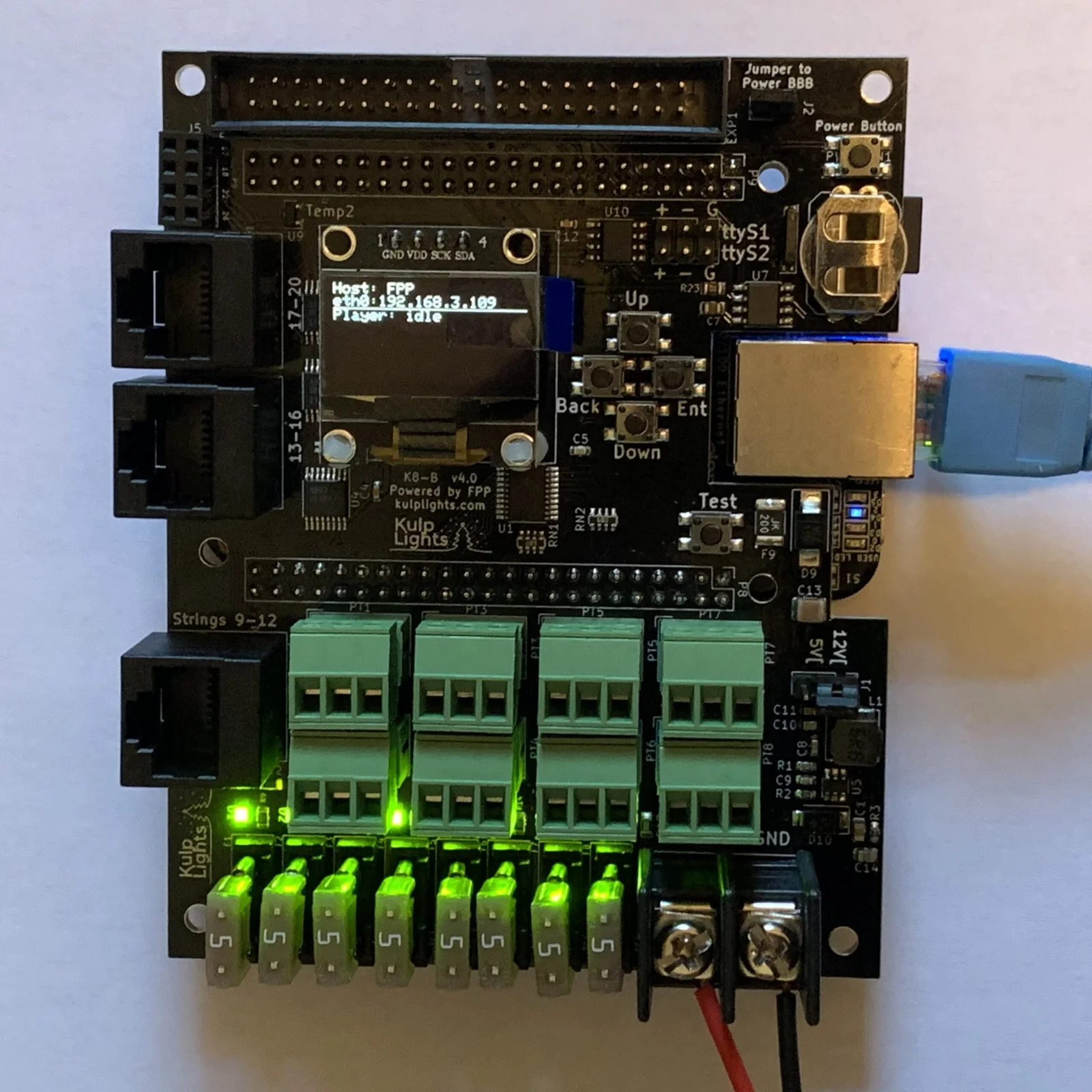
An early K8-B (v4.0) with a BeagleBone Black fitted. The current board differs in small details; the board map below shows it.
This page describes revision v4.3.1 (printed on the board as K8-B v4.3.1). All the v4.x
boards work the same way: the changes between them were mostly different clock and temperature
chips, used as parts shortages allowed.
How the K8-B differs from the PocketBeagle 2 boards
- It needs a BeagleBone Black (or a compatible BeagleBone). See BeagleBone Black.
- One power terminal, 5–18 V. It powers the controller and all eight ports, so all of them run at the same voltage. Don't use 24 V supplies.
- Mini-blade fuses, not eFuses: no per-port switching or current readings.
- Two DMX outputs on a 6-pin header, not RJ45 jacks.
- The differential ports are send-only. FPP drives this board with its BBB48String output: smart receivers work in v1, v2 or V4 mode. Falcon V5 receivers work in V4 mode, without status reports.
Specifications
| K8-B | |
|---|---|
| Local pixel ports | 8 (PT1–PT8), 3-pin 3.5 mm pluggable, plugs included |
| Port protection | 5 A mini-blade fuse per port, with a fuse-OK LED |
| Differential ports | 3 × RJ45 = 12 strings (9–20), send-only |
| Expansion port | 40-pin (2×20) header, 16 strings (21–36), for a Falcon F16v3 expansion board |
| Total strings | 36 |
| Power input | 1 terminal, 5–18 V DC, powers the controller and all 8 ports |
| DMX / serial | 2, RS-485 transmit, on a 2×3 header (ttyS1, ttyS2) |
| Audio | none built in. Use a USB sound card. |
| Ethernet & USB | the BeagleBone's own |
| Display & buttons | 128×64 OLED, Up / Down / Back / Enter / Test, Power |
| Real-time clock | yes, CR1220 backup cell |
| Temperature sensors | 2 (Temp1, Temp2) |
| Size | 86.4 × 108.9 mm (3.40 × 4.29 in), 7 mounting holes, 3.2 mm |
| FPP output | BBB48String |
| Requires | BeagleBone Black or compatible, FPP 9.5 or later |
Board map
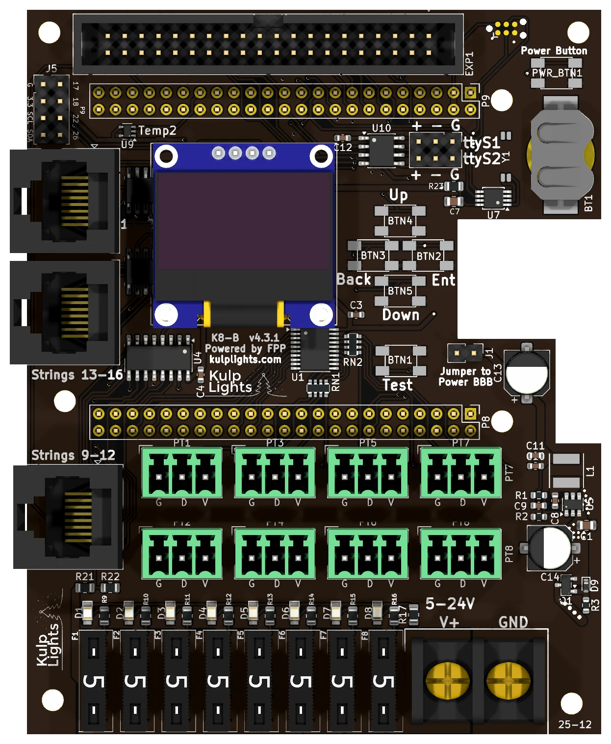
The BeagleBone sits under the upper part of the board, with its Ethernet jack in the notch in the right-hand edge.
Power terminal
The K8-B has one power terminal, on the bottom edge to the right of the fuses, marked V+ (left screw) and GND (right screw). It powers the BeagleBone and all of the logic, and every pixel port. FPP shows its voltage as VIN.
- Because every port shares this supply, all eight local strings must be the same voltage: 5 V or 12 V pixels. To mix voltages, put the other strings on differential receivers, which power their strings from their own supply.
- 18 V is the maximum. A 24 V supply will damage the board. (Some boards are printed
5-24V; use 18 V or less anyway.) - The terminal is rated 30 A. With eight ports fused at 5 A, add up your real loads and keep the total under that. Use 10 or 12 AWG wire for heavily loaded boards.
Check polarity before you power up
V+ is the left screw on the K8-B, the opposite of the K8-PB. The BeagleBone and the controller's logic are protected against a reversed supply, but the pixel ports aren't: a reversed supply goes straight through the fuses to every port and to any pixels connected.
See Power for supply sizing and safety.
Powering the BeagleBone: the "Power BBB" jumper
The jumper marked Jumper to Power BBB, to the right of the Test button, connects the board's 5 V regulator to the BeagleBone. It is fitted at the factory, and the BeagleBone then runs from the power terminal. Leave it fitted.
With the jumper removed, the BeagleBone isn't powered by the cape, and needs its own 5 V supply in its barrel jack. That isn't recommended. Never fit the jumper and plug a supply into the BeagleBone's barrel jack at the same time.
Pixel ports and fuses
The eight pixel ports are in two rows above the fuses:
| Top row | PT1 | PT3 | PT5 | PT7 |
| Bottom row | PT2 | PT4 | PT6 | PT8 |
Each port is G D V (ground, data, +V), as printed beneath it. PT1 is FPP port 1, and so on. See Pixel outputs.
Each port has its own 5 A mini-blade fuse, in a row along the bottom edge: F1 on the left for PT1, to F8 for PT8. The small LED above each fuse lights when the fuse is good and the board has power. An unlit LED means a blown or missing fuse. See Power → Fuses.
Differential ports
Three jacks on the left-hand edge, numbered from the bottom up:
| Position | Strings |
|---|---|
| top | 17-20 |
| middle | 13-16 |
| bottom, next to the pixel ports | 9-12 |
Each jack carries four strings. The ports are send-only. Any standard differential receiver works, and smart receivers work in v1, v2 or V4 mode (FPP drives this board with its BBB48String output). Falcon V5 receivers also work, set to V4, but they can't send status back. See Differential ports.
Expansion port (strings 21–36)
The 40-pin, 2×20 shrouded header along the top edge carries 16 more pixel data lines. It is compatible with Falcon F16v3 expansion boards, which turn the 16 lines into pixel ports with their own power.
| Pin | Signal | BeagleBone pin | Pin | Signal | BeagleBone pin |
|---|---|---|---|---|---|
| 1 | — | — | 2 | +5 V | — |
| 3 | GND | — | 4 | +5 V | — |
| 5 | GND | — | 6 | String 21 | P8-07 |
| 7 | GND | — | 8 | String 22 | P8-08 |
| 9 | GND | — | 10 | String 23 | P8-09 |
| 11 | GND | — | 12 | String 24 | P8-16 |
| 13 | GND | — | 14 | String 25 | P8-34 |
| 15 | GND | — | 16 | String 26 | P8-36 |
| 17 | GND | — | 18 | String 27 | P8-38 |
| 19 | GND | — | 20 | String 28 | P8-37 |
| 21 | GND | — | 22 | String 29 | P9-12 |
| 23 | GND | — | 24 | String 30 | P9-14 |
| 25 | GND | — | 26 | String 31 | P9-16 |
| 27 | GND | — | 28 | String 32 | P9-15 |
| 29 | GND | — | 30 | — | — |
| 31 | String 33 | P9-23 | 32 | String 34 | P8-11 |
| 33 | GND | — | 34 | String 35 | P8-12 |
| 35 | GND | — | 36 | String 36 | P8-15 |
| 37 | GND | — | 38 | GND | — |
| 39 | +5 V | — | 40 | +5 V | — |
Pin 1 is at the right-hand end of the header, on the outer (board-edge) row. String 33 is on pin 31, not pin 30: that is how the F16v3 expansion connector is laid out.
The data lines can also be used as GPIO inputs, the same way as on the K8-PB: leave a string at 0 pixels and its pin is free for FPP's GPIO Inputs, under the BeagleBone pin name. Wire buttons to switch the pin to GND and use the pull-up mode.
Not for pixels directly
The data lines on this header come straight from the BeagleBone at 3.3 V, with no buffering or protection. Always go through an expansion board, and never connect anything above 3.3 V.
DMX
The two DMX outputs share one 2×3 header, to the left of the battery holder, marked ttyS1 (top
row) and ttyS2 (bottom row):
| Row | + (left) |
- (middle) |
G (right) |
|---|---|---|---|
top: ttyS1 |
Data + | Data − | Ground |
bottom: ttyS2 |
Data + | Data − | Ground |
Wire + to XLR pin 3, − to pin 2 and G to pin 1 (or to an RJ45 DMX connector). The
outputs are transmit-only and can also drive Renard, LOR or Pixelnet through a suitable adapter.
FPP calls the ports ttyS1 and ttyS2. See DMX / serial.
Other connectors
| Connector | Marking | Details |
|---|---|---|
| OLED | GND VDD SCK SDA |
Controls & display |
| Buttons | Up Down Back Ent, Test |
the four menu buttons, with a separate Test button below them. Controls & display |
| Power button | Power Button |
top right corner. Shuts down or restarts the BeagleBone; see Power button. |
| GPIO / I²C | G 3.3 SCL SDA, P9 17 18 22 26 |
2×4 header, top left corner: 3.3 V, GND, the I²C bus and four BeagleBone pins (P9-17, P9-18, P9-22, P9-26), for extra I²C sensors or buttons to ground. 3.3 V only. |
| RTC battery | coin-cell holder, right edge | Clock |
FPP setup
When FPP detects the K8-B it sets itself up automatically. It enables the K8-B pixel-string
layout (FPP's BBB48String output, with all 36 strings: 100 pixels on each local port, none on
the rest), the voltage and temperature sensors, and two disabled DMX outputs on ttyS1 and
ttyS2. Set the pixel counts and start channels from xLights or the FPP Pixel Strings page. See
Configuring outputs.
Dimensions & mounting
- 86.36 × 108.86 mm (3.40 × 4.29 in), 7 plated mounting holes, 3.2 mm, for M3 (or #4) screws and standoffs: four in the corners, and three that line up with the BeagleBone's own holes.
- The BeagleBone hangs underneath the K8-B, so the standoffs in the corner holes must be tall enough to clear it and its connectors.