K40D-PB
Forty pixel strings from ten differential ports, for driving differential receivers. It has no local pixel ports.
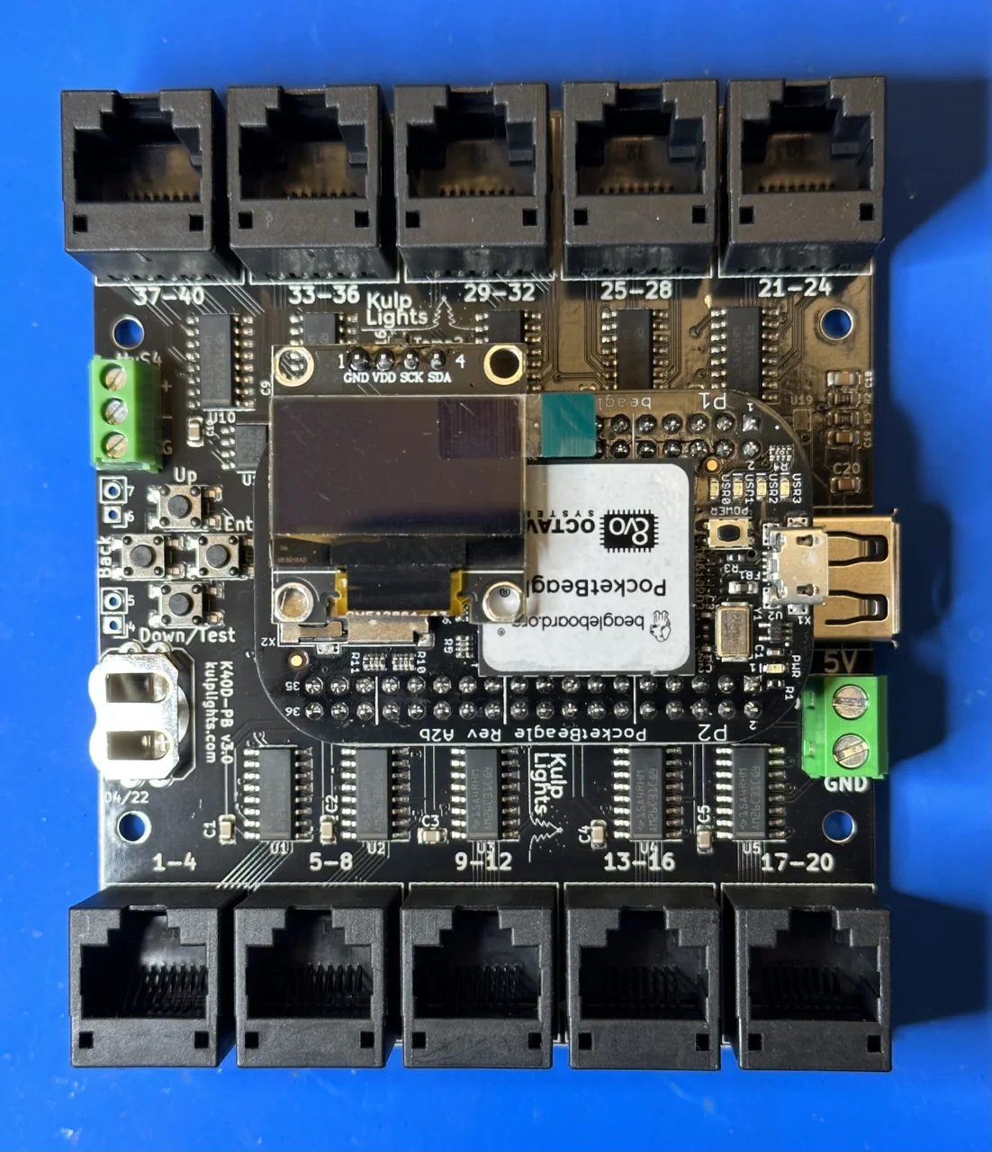
K40D-PB (v3.0) shown with an original PocketBeagle (PocketBeagle 1) fitted.
This page describes revision v3.0 (printed on the board as K40D-PB v3.0). Designed for the
original PocketBeagle, it works with both the PocketBeagle 2 and the PocketBeagle 1.
How the K40D-PB differs from the other boards
- Differential ports only. Every string goes out over an RJ45 to a differential receiver, which powers the pixels. There are no pixel plugs on the board.
- 5 V only. The board takes a regulated 5 V supply for the controller alone. Use one rated 4–5 A: the ten differential driver chips draw quite a bit.
- No Ethernet on the board. Plug a USB Ethernet adapter or an FPP-supported USB Wi-Fi adapter into its USB-A port. You need one of them to set it up.
- The USB-A port covers the PocketBeagle 2's SD card slot. Either use a PocketBeagle 2 Industrial, which runs FPP from its built-in eMMC, or fit the PB2 microSD extender, which clears the USB port.
- DMX is a 3-pin pluggable terminal, not an RJ45 jack.
Never connect the PocketBeagle's USB port to a computer
Don't power or set up the K40D-PB through the PocketBeagle's own USB port (USB tethering). It can permanently damage the K40D-PB. Power it only from its 5 V terminal, and set it up over a USB network adapter.
Specifications
| K40D-PB | |
|---|---|
| Local pixel ports | none |
| Differential ports | 10 × RJ45 = 40 strings (1–40), send-only |
| Power input | 5 V DC only, 2-pin 5.08 mm screw terminal (controller only) |
| DMX / serial | 1, RS-485 transmit, 3-pin 3.5 mm pluggable terminal (ttyS4) |
| Audio | none built in. Use a USB sound card. |
| Ethernet | none. Use a USB Ethernet or Wi-Fi adapter. |
| USB-A | 1 |
| Display & buttons | 128×64 OLED, Up / Down-Test / Enter / Back |
| Real-time clock | yes, CR1220 backup cell |
| Temperature sensors | 2 (Temp1, Temp2) |
| Size | 82.55 × 98.93 mm (3.25 × 3.89 in), 4 mounting holes, 3.0 mm |
| FPP output | BBB48String |
| Requires | PocketBeagle 2 (FPP 9.5 or later) or PocketBeagle 1 |
Board map
Power
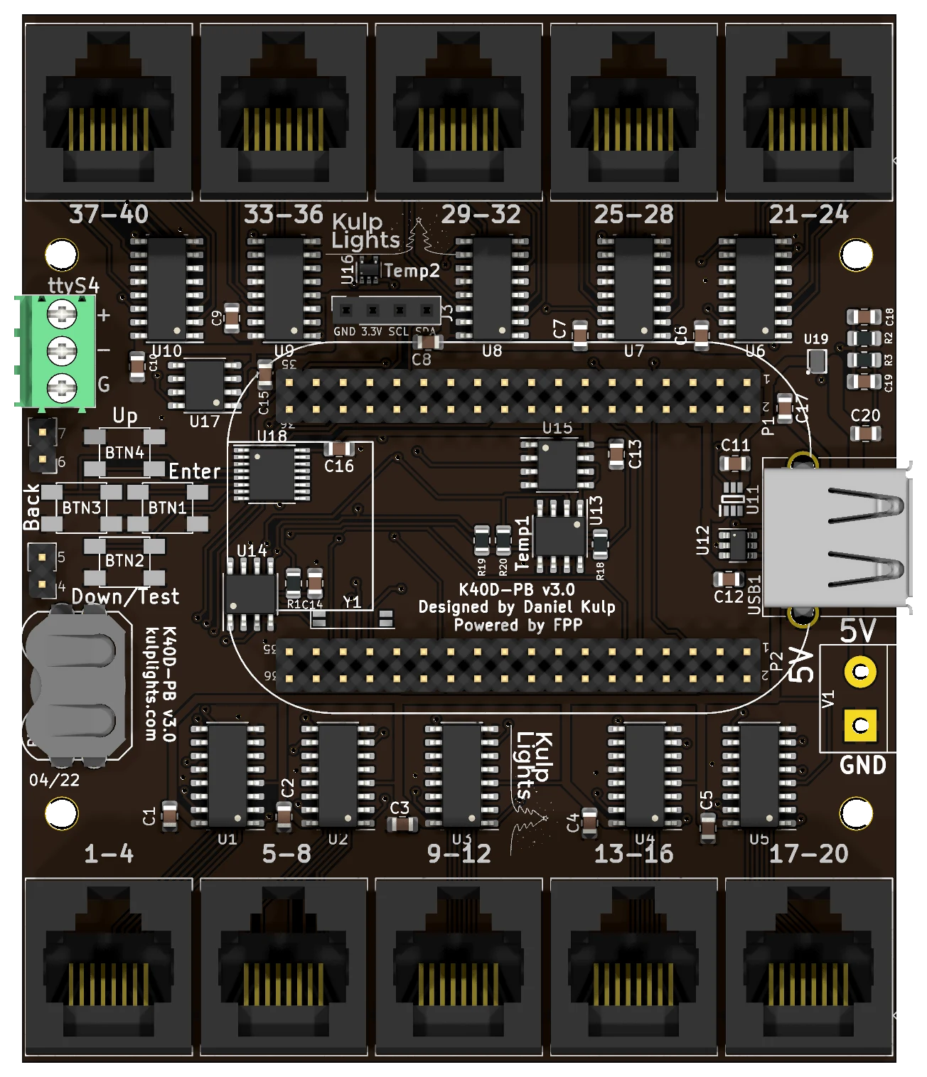
The power terminal is on the right-hand edge, marked 5V (upper screw) and GND (lower screw). It powers only the PocketBeagle, the USB port and the board's logic, including the ten differential driver chips, which draw quite a bit. Use a regulated 5 V supply rated 4–5 A. The receivers power the pixels from their own supplies. FPP shows no input voltage reading on this board.
5 V only
Use a regulated 5 V supply. Don't connect 12 V or 24 V to the K40D-PB.
Differential ports
Each jack carries four strings, numbered as printed beside it:
| Top row, left to right | 37-40 |
33-36 |
29-32 |
25-28 |
21-24 |
| Bottom row, left to right | 1-4 |
5-8 |
9-12 |
13-16 |
17-20 |
The ports are send-only, with the standard four-strings-per-RJ45 pinout. Any standard differential receiver works, and smart receivers work in v1, v2 or V4 mode (FPP drives this board with its BBB48String output, which has no V5). Each string can drive up to 800 pixels at 40 fps. See Differential ports.
DMX
DMX is on the 3-pin, 3.5 mm pluggable terminal at the top of the left edge, marked ttyS4:
| Pin | Marking | Signal | DMX XLR pin |
|---|---|---|---|
| top | + |
Data + | 3 |
| middle | - |
Data − | 2 |
| bottom | G |
Ground | 1 |
Wire it to an XLR or RJ45 DMX connector as above. The output is transmit-only and can also drive
Renard, LOR or Pixelnet through a suitable adapter. FPP calls the port ttyS4. See
DMX / serial.
DMX on a PocketBeagle 2 with an older EEPROM
On a PocketBeagle 2, FPP finds this DMX port through a mapping in the cape EEPROM, added in
EEPROM 3.0.1 (February 2025). On a board programmed before then, a DMX output on ttyS4
goes to the wrong serial port and nothing comes out. Fix it by updating the cape EEPROM under
Help → About → Cape Info (see Updating), or set the DMX output's
port to ttyS5 instead. On a PocketBeagle 1, ttyS4 always works.
Other connectors
| Connector | Marking | Details |
|---|---|---|
| USB-A | — | 1 port, right-hand edge, for the network adapter. It sits over the PocketBeagle 2's SD card slot. USB |
| OLED | GND 3.3V SCL SDA |
top centre. Controls & display |
| Buttons | Up Back Enter Down/Test |
Down and Test share one button. Controls & display |
| GPIO | 4 5, 6 7 |
two 2-pin header positions on the left edge, unpopulated (solder in pins to use them). They are four spare lines on the button I/O expander, which FPP lists as Exp.4–Exp.7 on a PocketBeagle 2 (pca9674-4 to pca9674-7 on a PocketBeagle 1). Like the Exp header lines they are 3.3 V, pull up weakly and can only sink current: use them for switches to ground. |
| RTC battery | coin-cell holder, bottom left | Clock |
FPP setup
When FPP detects the K40D-PB it sets itself up automatically. It enables the K40D-PB
pixel-string layout (FPP's BBB48String output, with all 40 strings at 50 pixels each), the
temperature sensors, and a disabled DMX output on ttyS4. Set the pixel counts and start channels
from xLights or the FPP Pixel Strings page. See Configuring outputs.
For the first setup, plug in a USB Ethernet adapter and connect it to your network, or use a USB Wi-Fi adapter and FPP's Wi-Fi hotspot.
Dimensions & mounting
- 82.55 × 98.93 mm (3.25 × 3.89 in), 4 mounting holes, 3.0 mm, for M2.5 (or #4) screws and standoffs.
- Use standoffs at least 6 mm (¼ in) tall, so nothing on the underside touches the enclosure.