K2-Pi0
The smallest controller: two eFused pixel ports with current monitoring, on a hat the size of a Raspberry Pi Zero.
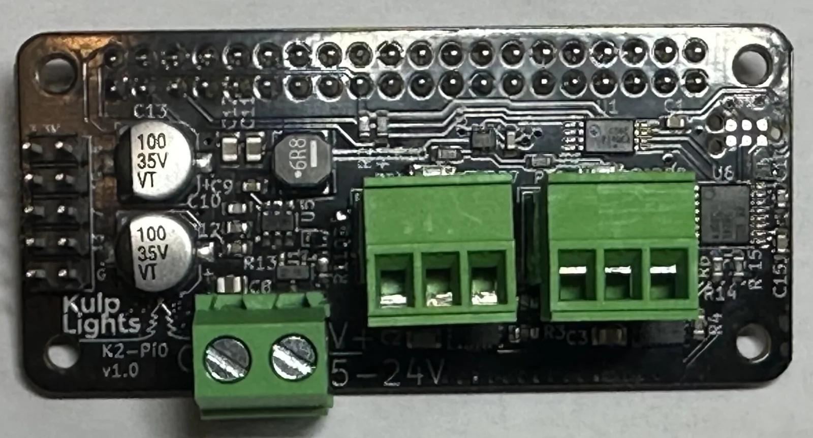
K2-Pi0 (v1.0).
This page describes revision v1.0 (printed on the board as K2-Pi0 v1.0), the only revision.
How the K2-Pi0 differs from the other boards
- It's made for a Raspberry Pi Zero 2 W. See Raspberry Pi and Fitting it to a Pi.
- No Ethernet: the Pi Zero 2 W has Wi-Fi only.
- No display or buttons, no DMX and no real-time clock. Set it up and control it from FPP's web page.
Specifications
| K2-Pi0 | |
|---|---|
| Local pixel ports | 2 (PT1, PT2), 3-pin 3.5 mm pluggable, plugs included |
| Port protection | eFuse per port, about 6 A, latching |
| Power switching | per port (FPP-controlled) |
| Current monitoring | both ports |
| Pixels per string | up to 1600; about 800 at 40 fps |
| Power input | 1 terminal, 5–24 V DC, powers the Pi and both ports |
| DMX / serial | none |
| Network | the Pi's Wi-Fi |
| Display & buttons | none |
| Real-time clock | none |
| Size | 65 × 30 mm (2.56 × 1.18 in), 4 mounting holes, 2.7 mm |
| FPP output | DPIPixels |
| Requires | Raspberry Pi Zero 2 W (see below for other Pis), FPP 10 or later |
Board map
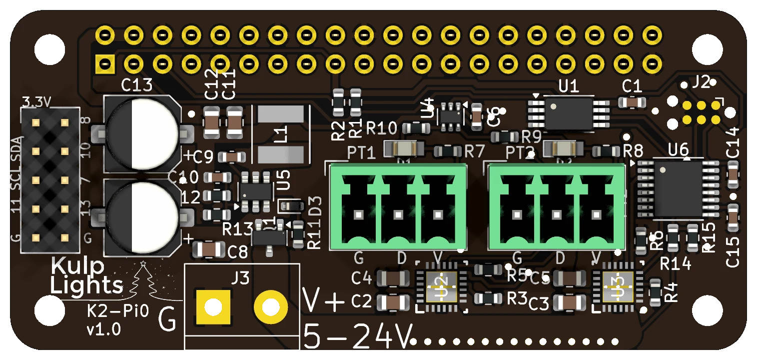
Power terminal
The power terminal is at the bottom left, marked G (left screw) and V+ 5-24V (right screw). It powers the Pi and both pixel ports. FPP shows its voltage as VIN.
- The pixels run at the supply voltage, so both strings must match it: 5, 12 or 24 V.
- With a 5 V supply, turn its output up to about 5.3 V so the Pi gets a full 5 V; see Raspberry Pi → Powering.
- The Pi is protected against a reversed supply, but the pixel ports aren't. Check the polarity before you power up.
- Don't plug a supply into the Pi's own USB power socket while the K2-Pi0 is powered.
Pixel ports
The two pixel ports, PT1 (left) and PT2 (right), are in the middle of the board. Each is G D V (ground, data, +V), as printed beneath it. Each string can have up to 1600 pixels; see Raspberry Pi → Pixel outputs.
Each port has its own eFuse, which trips at about 6 A and latches off, and FPP reads both ports' current. When an eFuse trips, FPP marks the port with a red icon on Status/Control → Port Status; click it to turn the port back on once the fault is fixed. The green LED beside each port lights when the port has power. See Current monitoring.
GPIO / I²C header
The 2×5 header at the left-hand end brings out 3.3 V, ground, the I²C bus and five Pi GPIO pins, numbered on the board by their Pi header pin: 7, 8, 10, 11 and 13. Use them in FPP's GPIO Inputs for buttons or switches to ground, or add an I²C display or clock module. They are 3.3 V only.
Fitting it to a Pi
On a Pi Zero 2 W (or Zero W), the K2-Pi0's four holes line up with the Pi's: fix them together with M2.5 standoffs.
It also works on the bigger Pis (3 B+, 4, 5), but there its holes don't line up with anything. The board is held only by the GPIO header, so make sure it can't tip or press down onto the Pi, where it could short something out. Support it with something insulating, and keep it clear of the Pi's components.
FPP setup
When FPP detects the K2-Pi0 it sets itself up automatically. It enables the K2-Pi0 pixel-string layout (FPP's DPIPixels output, with 100 pixels on each port) and the voltage and current sensors. Set the pixel counts and start channels from xLights or the FPP Pixel Strings page. See Configuring outputs.
For the first setup, connect to FPP's Wi-Fi hotspot and join the Pi to your Wi-Fi network. Because the board has no clock, set up NTP under Settings → Time so schedules run at the right time.
Dimensions & mounting
- 65 × 30 mm (2.56 × 1.18 in), 4 holes, 2.7 mm, for M2.5 screws, on the Pi Zero's hole pattern.