OctoPlus
Eight HUB75 outputs for LED panel matrices on a BeagleBone Black: an updated version of the classic "Octoscroller" cape, with a clock, a temperature sensor, an OLED and buttons.
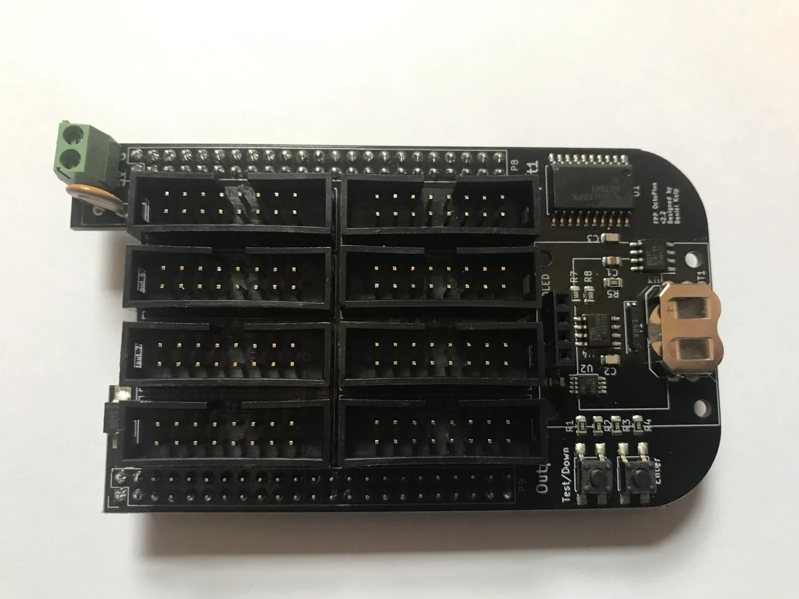
An early OctoPlus (v2.2), without the OLED fitted. The board map below shows the current board.
This page describes revision v2.3.1 (printed on the board as OctoPlus v2.3.1). See
Board revisions for the earlier boards.
How the OctoPlus differs from the other boards
- It needs a BeagleBone Black (or a compatible BeagleBone). See BeagleBone Black.
- 5 V only. The terminal powers the BeagleBone and the cape. The panels need their own 5 V supply.
- No E line, so 1/32-scan panels (such as 64×64 1/32) don't work. 1/16-scan and lower do.
- No mounting holes. The cape is held by its headers on the BeagleBone; mount the BeagleBone.
Specifications
| OctoPlus | |
|---|---|
| LED panel outputs | 8 × HUB75 (Output 1–8), no E line |
| Panels | P10 (32×16, 1/4 or 1/8 scan) and P5 (64×32, 1/8 or 1/16 scan), and other 1/16-scan or lower panels |
| Power input | 5 V DC only, 2-pin 3.5 mm screw terminal |
| DMX / serial | none |
| Audio | none built in. Use a USB sound card. |
| Ethernet & USB | the BeagleBone's own |
| Display & buttons | 128×64 OLED, Test-Down / Enter |
| Real-time clock | yes, CR1220 backup cell |
| Temperature sensor | yes |
| Size | 55.4 × 98.6 mm (2.18 × 3.88 in), no mounting holes |
| FPP output | LED Panels (BeagleBone, Octoscroller v2 wiring) |
| Requires | BeagleBone Black or compatible, FPP 9.5 or later |
Board map
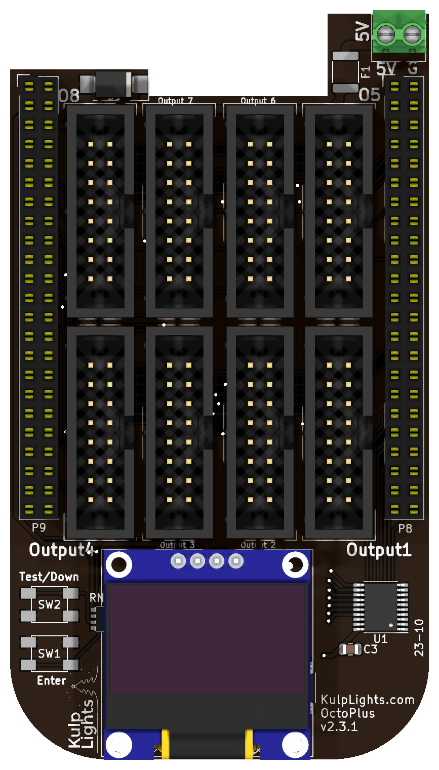
Shown with the BeagleBone's Ethernet jack at the top, in the notch beside the power terminal.
Power
The power terminal is on the tab at the top-right corner, marked 5V (left screw) and G (right screw).
- It powers the BeagleBone and the cape. Use a regulated 5 V supply rated at least 2 A, more if you plug anything into the BeagleBone's USB port.
- The panels are not powered through the OctoPlus. Run each panel's power from your 5 V panel supply. You can feed the OctoPlus from the same supply.
- There are no power LEDs. When the board is running, the OLED shows status.
5 V only
The OctoPlus has no voltage regulator. A 12 V or 24 V supply, or a reversed one, makes the protection clamp conduct and trip the resettable fuse, and can damage the board.
Panel outputs
The eight outputs are in two rows of four between the BeagleBone's headers. With the Ethernet jack at the top:
| Top row | Output 8 | Output 7 | Output 6 | Output 5 |
| Bottom row | Output 4 | Output 3 | Output 2 | Output 1 |
Each is a standard HUB75 connector, except that pin 8 is ground instead of E:
| Pin | Signal | Pin | Signal |
|---|---|---|---|
| 1 | R1 | 2 | G1 |
| 3 | B1 | 4 | GND |
| 5 | R2 | 6 | G2 |
| 7 | B2 | 8 | GND (no E) |
| 9 | A | 10 | B |
| 11 | C | 12 | D |
| 13 | CLK | 14 | LAT |
| 15 | OE | 16 | GND |
- Use the ribbon cables that come with your panels. The red stripe goes to pin 1 (marked on the header's shroud).
- FPP allows up to 16 panels per output. The refresh rate depends on the longest chain and on the colour depth; see Capacity & refresh rate.
- On a SanCloud BeagleBone Enhanced, Output 5 doesn't work properly.
Other connectors
| Connector | Marking | Details |
|---|---|---|
| OLED | GND VDD SCK SDA |
bottom centre. Controls & display |
| Buttons | Test/Down, Enter |
bottom left corner. Controls & display |
| RTC battery | coin-cell holder under the OLED | unplug the OLED to change the cell. Clock |
The OctoPlus has no Power button. Use FPP's Shutdown, then switch off the supply.
Capacity & refresh rate
How many panels you can run depends on how long each chain is and on the colour depth. The table gives the full-frame refresh rate in Hz for 64×32 1/16-scan panels with all eight outputs in use, measured on an OctoPlus at FPP's default brightness (10). Bold values are 60 Hz or more. Italic values are under 60 Hz, where flicker starts to show on camera and to some viewers.
| Panels per output | Total panels | 12-bit | 10-bit | 8-bit | 6-bit |
|---|---|---|---|---|---|
| 1 | 8 | 111 | 132 | 212 | 257 |
| 2 | 16 | 79 | 95 | 138 | 177 |
| 3 | 24 | 59.9 | 73 | 99 | 130 |
| 4 | 32 | 48 | 58 | 74 | 96 |
| 5 | 40 | 40 | 48 | 60 | 78 |
| 6 | 48 | 34 | 41 | 50 | 65 |
| 8 | 64 | 26 | 30 | 38 | 49 |
| 10 | 80 | 20 | 24 | 30 | 39 |
| 12 | 96 | 17 | 21 | 26 | 34 |
| 16 | 128 | 13 | 16 | 19 | 26 |
- Rule of thumb at 60 Hz with 64×32 panels: 2–3 panels per output at 12-bit colour, or 5 per output at 8-bit (40 panels).
- Smaller panels go further. A 32×16 P10 panel holds a quarter of the pixels of a 64×32, so a chain of P10s refreshes about as fast as a chain of a quarter as many 64×32s.
- Refresh depends on the longest chain. Spread the panels evenly across the outputs.
- A single chain on Output 1 runs up to twice as fast, because Output 1 shares its I/O bank with the panel control lines. Adding a second output costs most of that gain; going from 2 to 8 outputs costs only another 10–15 %.
- These are worst-case figures, measured with random pixel data. Frames with flat or solid areas refresh faster: a solid fill ran 44 % faster at 3 panels per output, 8-bit.
- 1/8-scan outdoor panels refresh about the same from 4 panels per output up, and faster on shorter chains (158 Hz at 1 panel per output, 12-bit).
- Lowering the colour depth is the easiest way to win back refresh on long chains. Unlike the PocketScroller v3, a lower brightness setting lowers the refresh rate a little on the OctoPlus.
FPP setup
When FPP detects the OctoPlus it sets up an LED Panels output (Input/Output Setup → Channel Outputs → LED Panels) with the OctoPlus wiring, starting with one 32×16 1/8-scan panel on Output 1. Change it to match your panels:
- Set the panel size and scan (e.g. 32×16 1/8, 64×32 1/16).
- Set the layout: how many panels wide and high.
- In the grid, assign each panel to an output and a position in the chain, and set its orientation.
- Set colour depth and brightness, then save. FPP restarts the output.
See LED panel matrices in the FPP manual for every field.
Board revisions
The revision is printed on the board next to the name. Every revision uses the same FPP setup.
| Revision | Changes |
|---|---|
| v2.2x | The early boards. The panel lines come straight from the BeagleBone. |
| v2.3 | Adds a 5 V buffer for the panels' clock, latch, OE and row-select lines, for more reliable panel driving. |
| v2.3.1 | Current board. |
Dimensions & mounting
- 55.37 × 98.55 mm (2.18 × 3.88 in), with a notch for the BeagleBone's Ethernet jack, a tab for the power terminal, and rounded corners at the far end.
- No mounting holes. The OctoPlus is held by its headers on the BeagleBone, so mount the BeagleBone by its own holes.