K64D-B
Sixty-four pixel strings from sixteen differential ports, for driving differential receivers, plus two DMX/LOR outputs, built-in audio and an FM transmitter socket. It has no local pixel ports.
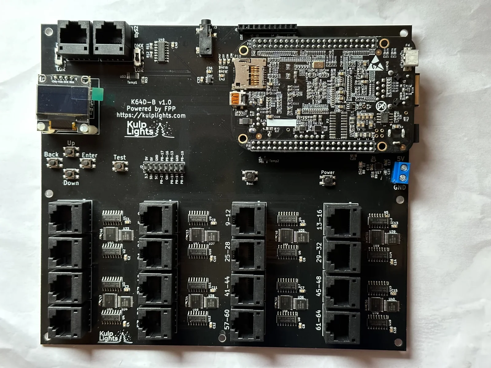
K64D-B (v1.0) with a BeagleBone Black fitted upside down.
This page describes revision v1.0 (printed on the board as K64D-B v1.0), the only revision.
How the K64D-B differs from the other boards
- It needs a BeagleBone Black (or a compatible BeagleBone), which plugs in upside down on top of the cape. See BeagleBone Black.
- Differential ports only. Every string goes out over an RJ45 to a differential receiver, which powers the pixels. There are no pixel plugs on the board.
- 5 V only. The board takes a regulated 5 V supply for the controller alone.
- The differential ports are send-only: smart receivers work in v1, v2 or V4 mode. Falcon V5 receivers work in V4 mode, without status reports.
Specifications
| K64D-B | |
|---|---|
| Local pixel ports | none |
| Differential ports | 16 × RJ45 = 64 strings (1–64), send-only |
| Power input | 5 V DC only, 2-pin 5.08 mm screw terminal (controller only) |
| DMX / serial | 2, RS-485 transmit, on RJ45 jacks with a DMX/LOR switch (ttyS1, ttyS2) |
| Audio | built-in stereo DAC, 3.5 mm line out, FM transmitter socket |
| GPIO header | 2×8: 3.3 V, 5 V, GND, I²C and 8 BeagleBone pins |
| Ethernet & USB | the BeagleBone's own |
| Display & buttons | 128×64 OLED, Up / Down / Back / Enter / Test, Boot, Power |
| Real-time clock | yes, CR1220 backup cell |
| Temperature sensors | 2 (Temp1, Temp2) |
| Size | 182.0 × 159.6 mm (7.17 × 6.28 in), 7 mounting holes, 3.2 mm |
| FPP output | BBShiftString |
| Requires | BeagleBone Black or compatible, FPP 9.5 or later |
Board map
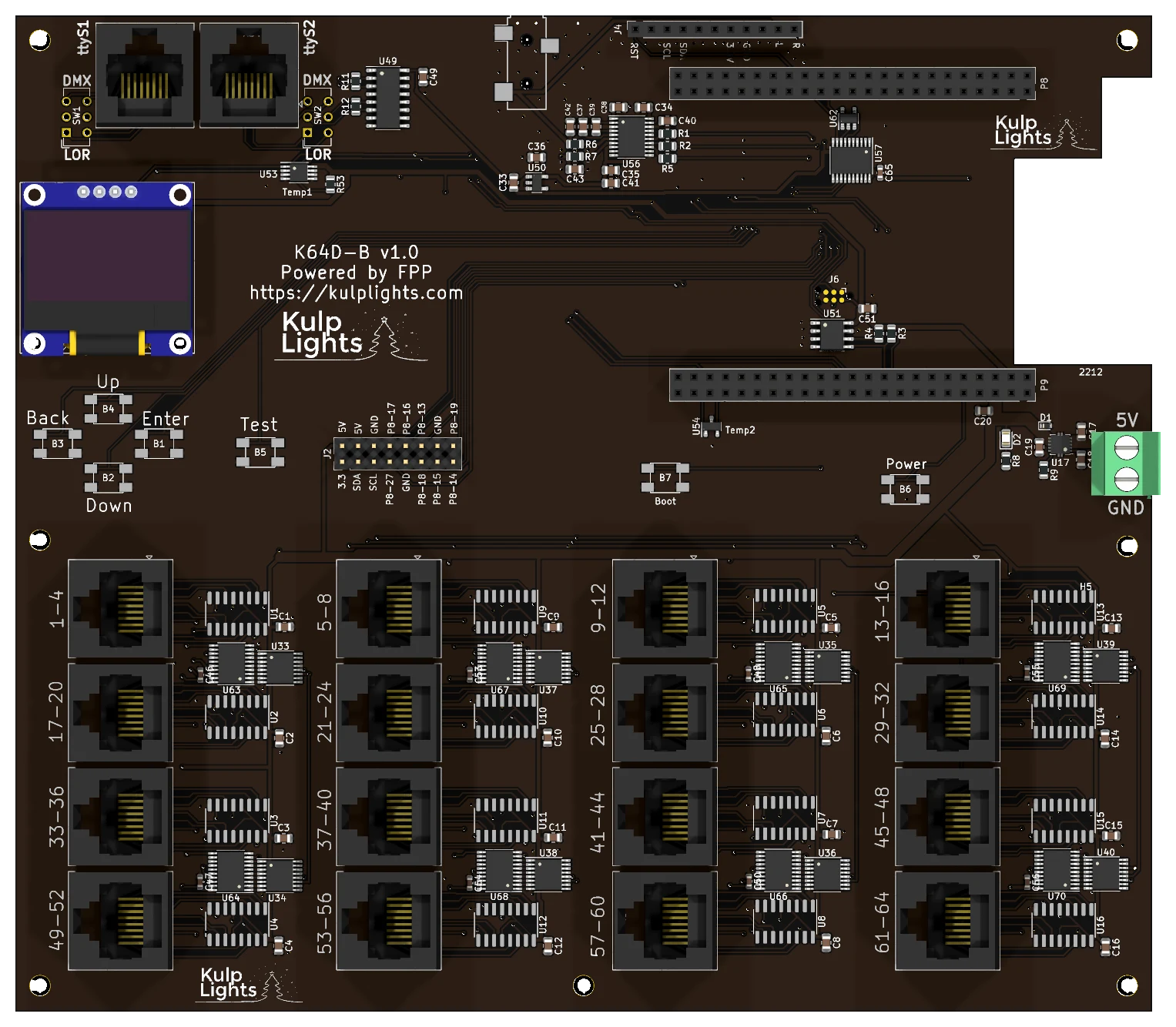
The BeagleBone mounts upside down over the two long headers at the top right, with its Ethernet jack over the notch in the right-hand edge.
Power
The power terminal is on the right-hand edge, below the BeagleBone, marked 5V (upper screw) and GND (lower screw). It powers the BeagleBone and all of the logic, including the sixteen differential driver chips. The receivers power the pixels from their own supplies. Use a regulated 5 V supply rated at least 3 A. The LED beside the terminal lights when the board has power. FPP shows no input voltage reading on this board.
5 V only, and check the polarity
Use a regulated 5 V supply. The input is protected against over-voltage and overload, but not against a reversed supply: check that 5 V goes to the upper screw before you switch on. Don't connect 12 V or 24 V.
Differential ports
The sixteen jacks are in a 4 × 4 grid on the lower part of the board. Each carries four strings, numbered as printed beside it, across each row and then down:
| Row 1 (top) | 1-4 |
5-8 |
9-12 |
13-16 |
| Row 2 | 17-20 |
21-24 |
25-28 |
29-32 |
| Row 3 | 33-36 |
37-40 |
41-44 |
45-48 |
| Row 4 (bottom) | 49-52 |
53-56 |
57-60 |
61-64 |
The ports are send-only, with the standard four-strings-per-RJ45 pinout. Any standard differential receiver works, and smart receivers work in v1, v2 or V4 mode; with v2 you can chain up to six receivers on a port. Falcon V5 receivers also work, set to V4, but they can't send status back. See Differential ports.
Each string can drive up to 800 pixels at 40 fps, or 1600 at 20 fps. All the strings are sent together, so the longest string sets the frame rate for the whole board.
DMX / LOR
The two serial outputs are RJ45 jacks at the top-left corner: ttyS1 on the left and ttyS2 on
the right. Each has a small slide switch beside it:
| Switch | RJ45 pins | Use |
|---|---|---|
| DMX (up) | Data + on pin 1, Data − on pin 2, ground on 7 and 8 | DMX over RJ45, Renard, Pixelnet |
| LOR (down) | Data + on pin 4, Data − on pin 5, ground on 7 and 8 | Light-O-Rama networks: plug straight into LOR controllers |
The outputs are transmit-only. FPP calls them ttyS1 and ttyS2. See
DMX / serial.
Audio and FM transmitter
The board has a built-in PCM5102A stereo DAC. Its 3.5 mm line-out jack is on the top edge,
and the FM transmitter socket (RST … L R) is beside it, for an optional Si4713 module. See
Audio.
GPIO header
The 2×8 header beside the Test button brings out power, the I²C bus and eight BeagleBone pins, for extra buttons, switches or I²C sensors:
| Pin | Signal | Pin | Signal |
|---|---|---|---|
| 1 | 3.3 V | 2 | 5 V |
| 3 | SDA | 4 | 5 V |
| 5 | SCL | 6 | GND |
| 7 | P8-27 | 8 | P8-17 |
| 9 | GND | 10 | P8-16 |
| 11 | P8-18 | 12 | P8-13 |
| 13 | P8-15 | 14 | GND |
| 15 | P8-14 | 16 | P8-19 |
Pin 1 is at the bottom left; the signal names are printed above and below the pins. Use the pins in FPP's GPIO Inputs, under their BeagleBone names. They connect straight to the BeagleBone, so they are 3.3 V only: wire buttons to switch a pin to GND and use the pull-up mode.
Buttons
| Button | Details |
|---|---|
Up Down Back Enter |
the menu buttons, at the left below the OLED. Controls & display |
Test |
to the right of the menu buttons. Test button |
Boot |
below the BeagleBone. Hold it at power-on to boot an older BeagleBone from its SD card; see Booting from the SD card. Pressing it while the board is running briefly glitches strings 9–12 and 25–28. |
Power |
left of the power terminal. Shuts down or restarts the BeagleBone; see Power button. |
Other connectors
| Connector | Marking | Details |
|---|---|---|
| OLED | GND VDD SCK SDA |
top left. Controls & display |
| RTC battery | coin-cell holder under the OLED | unplug the OLED to change the cell. Clock |
FPP setup
When FPP detects the K64D-B it sets itself up automatically. It enables the K64D-B
pixel-string layout (FPP's BBShiftString output, with all 64 strings at 100 pixels each), the
built-in audio, the temperature sensors, the FM transmitter plugin's settings, and two disabled DMX
outputs on ttyS1 and ttyS2. Set the pixel counts and start channels from xLights or the FPP
Pixel Strings page. See Configuring outputs.
Dimensions & mounting
- 182.0 × 159.55 mm (7.17 × 6.28 in), 7 plated mounting holes, 3.2 mm, for M3 (or #4) screws and standoffs.
- Use standoffs at least 6 mm (¼ in) tall, so nothing on the underside touches the enclosure.