K4-PB
The smallest pixel controller: 4 eFused pixel ports with per-port current monitoring and a DMX header, on a 71 × 67 mm board that fits a small TA-200 enclosure.
This page describes revision v3.0.1 (printed on the board as K4-PB v3.0.1). The K4-PB works
with both the PocketBeagle 2 and the original PocketBeagle 1, and nothing blocks the SD card
slot.
How the K4-PB differs from the K8, K16 and K32 boards
- No Ethernet on the board. Plug a USB Ethernet adapter or an FPP-supported USB Wi-Fi adapter into its USB-A port. You need one of them to set it up. A "nano" or "mini" Wi-Fi adapter fits inside a TA-200 enclosure.
- One power terminal, 5 or 12 V. It powers the controller and all four ports, so all of them run at the same voltage. 18 V is the absolute maximum; don't use 24 V supplies.
- No differential ports and no expansion port. It drives only its four local ports.
- DMX is a 3-pin header, not an RJ45 jack.
- No real-time clock. The board gets the time from the network (NTP).
- Not protected against a reversed supply. Check the polarity before you power up.
PocketBeagle 1: never connect its USB port to a computer
With an original PocketBeagle 1 fitted, don't power or set up the K4-PB through the PocketBeagle's own USB port (USB tethering). It can permanently damage the K4-PB. Power it only from its power terminal, and set it up over a USB network adapter. With a PocketBeagle 2, USB tethering is safe.
Specifications
| K4-PB | |
|---|---|
| Local pixel ports | 4 (PT1–PT4), 3-pin 3.5 mm pluggable, plugs included |
| Port protection | eFuse per port, about 5.2 A, latching |
| Power switching | per port (FPP-controlled) |
| Current monitoring | every port |
| Differential ports | none |
| Total strings | 4 |
| Power input | 1 terminal, 5 or 12 V DC (18 V maximum), powers the controller and all 4 ports |
| DMX / serial | 1, RS-485 transmit, 3-pin 2.54 mm header (ttyS4) |
| GPIO header | 2×4, unpopulated: 3.3 V, GND and six PocketBeagle pins (P1-2 to P1-12) |
| Audio | none built in. Use a USB sound card. |
| Ethernet | none. Use a USB Ethernet or Wi-Fi adapter. |
| USB-A | 1 |
| Display & buttons | 128×64 OLED, Test-Down / Enter |
| Real-time clock | none |
| Temperature sensor | yes |
| Size | 71.1 × 67.1 mm (2.80 × 2.64 in), 3 mounting holes, 4.0 mm |
| FPP output | BBB48String |
| Requires | PocketBeagle 2 (FPP 9.5 or later recommended; any 9.x works) or PocketBeagle 1 |
Board map
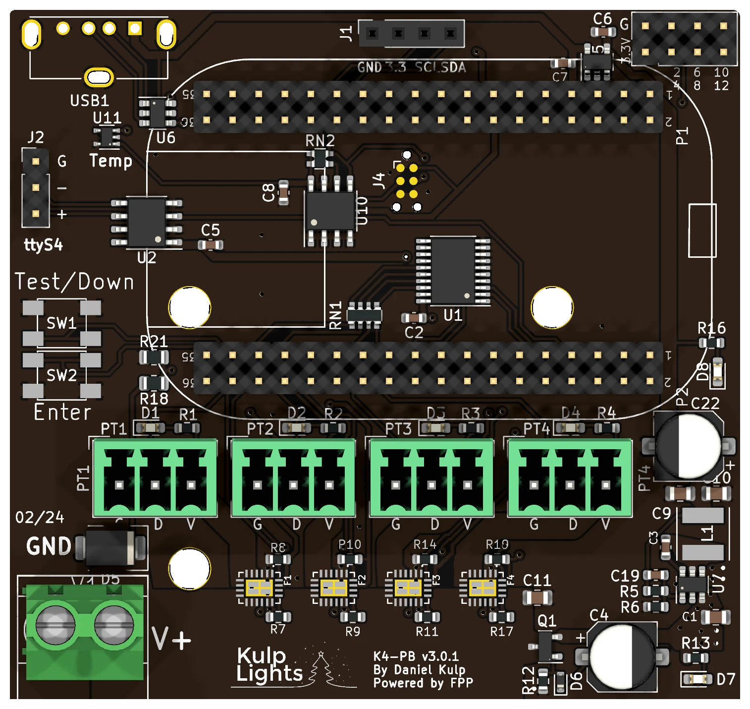
Power terminal
The power terminal is at the bottom left: GND on the left screw, V+ on the right. It powers the PocketBeagle, the USB port and all of the logic, and all four pixel ports. FPP shows its voltage as VIN.
- Every port shares this supply, so all four strings must be the same voltage: 5 V or 12 V pixels.
- 18 V is the maximum. A 24 V supply will damage the board.
- Two blue LEDs on the right-hand edge show that the board has power and that its internal 5 V supply is running.
Check polarity before you power up
The K4-PB is not protected against a reversed supply. The controller's own logic is protected, but a supply wired backwards drives the input surge-protection diode, which is likely to burn out. It usually fails as a short, and the board then won't power up until it is repaired.
Pixel ports
The four pixel ports are in a row across the middle of the board, PT1 on the left to PT4 on the right. Each is G D V (ground, data, +V), as printed beneath it. PT1 is FPP port 1, and so on. See Pixel outputs.
eFuses and current monitoring
Every port has its own eFuse, which trips at about 5.2 A and latches off. FPP reads every port's current and turns each port on and off as needed. When an eFuse trips, FPP marks the port with a red icon on Status/Control → Port Status; click it to turn the port back on once the fault is fixed. See Current monitoring.
DMX
DMX is on the 3-pin, 2.54 mm header on the left edge, marked ttyS4:
| Pin | Marking | Signal | DMX XLR pin |
|---|---|---|---|
| top | G |
Ground | 1 |
| middle | - |
Data − | 2 |
| bottom | + |
Data + | 3 |
Make up a cable from a 3-pin socket to an XLR or RJ45 DMX connector, wired as above. The output
is transmit-only and can also drive Renard, LOR or Pixelnet through a suitable adapter. FPP calls
the port ttyS4. See DMX / serial.
DMX on a PocketBeagle 2 with an older EEPROM
On a PocketBeagle 2, FPP finds this DMX port through a mapping in the cape EEPROM, added in
EEPROM 3.0.1 (February 2025). On a board programmed before then, a DMX output on ttyS4
goes to the wrong serial port and nothing comes out. Fix it by updating the cape EEPROM under
Help → About → Cape Info (see Updating), or set the DMX output's
port to ttyS5 instead. On a PocketBeagle 1, ttyS4 always works.
GPIO header
The 2×4 header position at the top right is not fitted: solder in a 2×4, 2.54 mm pin header if you want to use it. It brings out 3.3 V, GND and six PocketBeagle pins, numbered on the board: P1-2, P1-4, P1-6, P1-8, P1-10, P1-12. Use them in FPP's GPIO Inputs for buttons or switches to ground. They connect straight to the PocketBeagle, so they are 3.3 V only; never connect 5 V or anything higher.
Other connectors
| Connector | Marking | Details |
|---|---|---|
| USB-A | — | 1 port, top left, for the network adapter. USB |
| OLED | GND 3.3 SCL SDA |
Controls & display |
| Buttons | Test/Down Enter |
Down and Test share one button. Controls & display |
FPP setup
When FPP detects the K4-PB it sets itself up automatically. It enables the K4-PB pixel-string
layout (FPP's BBB48String output), with each port set to 100 WS2811 pixels at 50 % brightness,
the voltage, current and temperature sensors, and a disabled DMX output on ttyS4. Set the pixel
counts and start channels from xLights or the FPP Pixel Strings page. See
Configuring outputs.
For the first setup, plug in a USB Ethernet adapter and connect it to your network, or use a USB Wi-Fi adapter and FPP's Wi-Fi hotspot. Because the board has no clock, set up NTP under Settings → Time so schedules run at the right time.
Dimensions & mounting
- 71.12 × 67.06 mm (2.80 × 2.64 in), 3 mounting holes, 4.0 mm, for M3 or M3.5 (or #6) screws.
- Designed to fit a TA-200 enclosure.
- Use standoffs at least 6 mm (¼ in) tall, so nothing on the underside touches the enclosure.